Eureka AIR delivers breakthrough ideas for toughest innovation challenges, trusted by R&D personnel around the world.

Method for working an apparatus having at least one electrical layer structure, and component arrangement for working an apparatus having at least one electrical layer structure

Active Publication Date: 2018-02-06
DOLYA HOLDCO 5 LTD
View PDF11 Cites 0 Cited by
  • Summary
  • Abstract
  • Description
  • Claims
  • Application Information

AI Technical Summary

Benefits of technology

The patent text describes a method for making electronic components using a special layer structure. This method allows for the production of components using alternative methods and simplified process conditions. The plastic cap protects the LED chip from external harmful influences during manufacture and operation. Additionally, the method reduces the minimum voltage required to cause electrical breakdown of the insulating layer and improves the smoothness of the electrically conductive layer.

Problems solved by technology

In this case, the dielectric oxide layer can form a contact resistance and lead to a voltage drop and / or conversion of electrical energy into heat, that is to say lead to an energy loss.

Method used


Image

  • Method for working an apparatus having at least one electrical layer structure, and component arrangement for working an apparatus having at least one electrical layer structure
  • Method for working an apparatus having at least one electrical layer structure, and component arrangement for working an apparatus having at least one electrical layer structure
  • Method for working an apparatus having at least one electrical layer structure, and component arrangement for working an apparatus having at least one electrical layer structure

Examples


Embodiment Construction

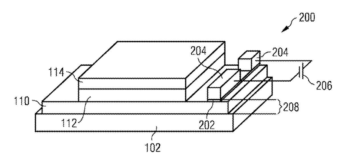
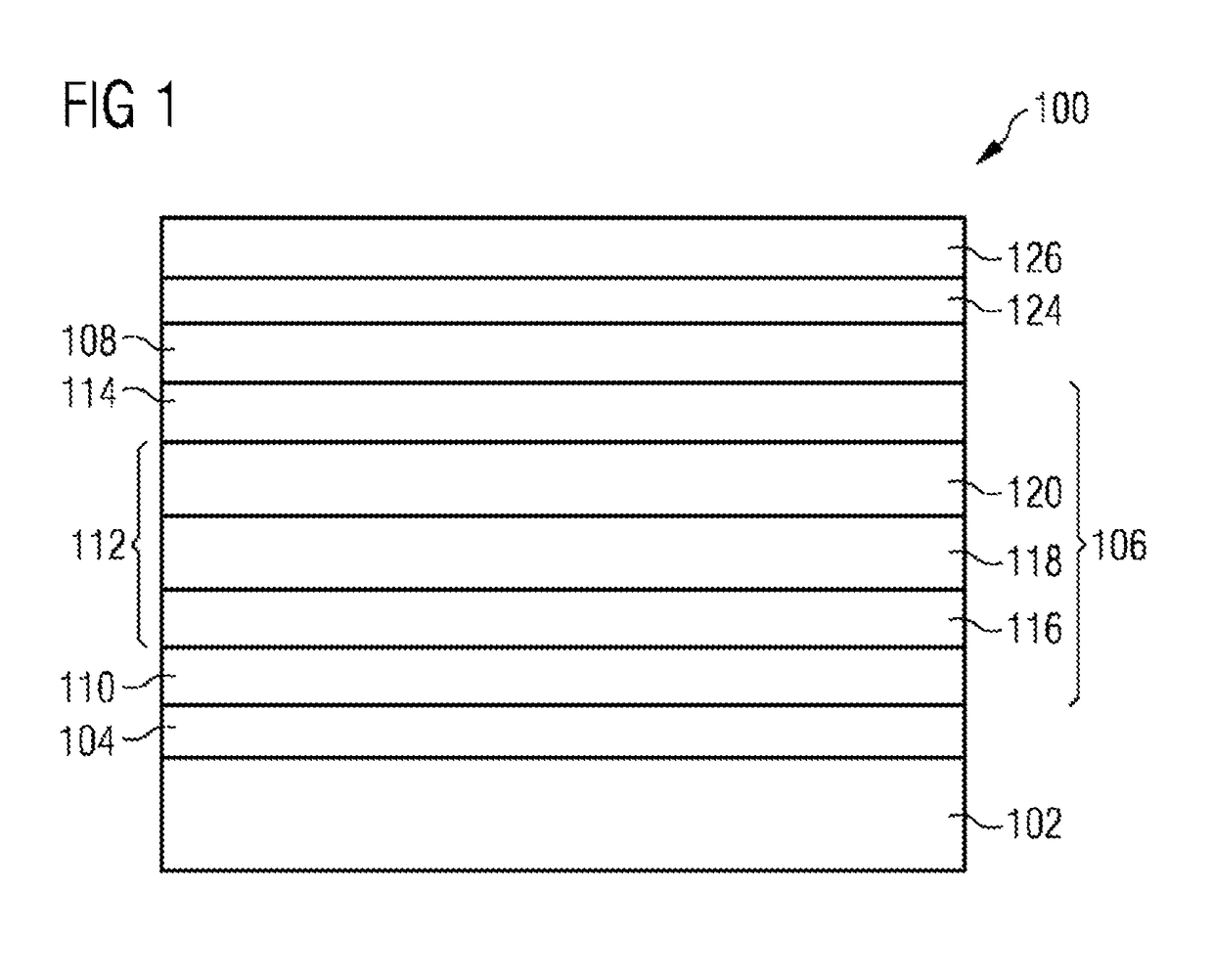
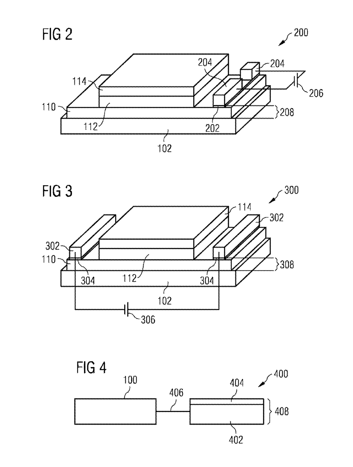
[0097]In the following detailed description, reference is made to the accompanying drawings, which form part of this description and show for illustration purposes specific embodiments in which the invention can be implemented. In this regard, direction terminology such as, for instance, “at the top”, “at the bottom”, “at the front”, “at the back”, “front”, “rear”, etc. is used with respect to the orientation of the figure(s) described. Since component parts of embodiments can be positioned in a number of different orientations, the direction terminology serves for illustration and is not restrictive in any way whatsoever. It goes without saying that other embodiments can be used and structural or logical changes can be made, without departing from the scope of protection of the present invention. It goes without saying that the features of the various embodiments described herein can be combined with one another, unless specifically indicated otherwise. Therefore, the following det...


PUM

PropertyMeasurementUnit
Electric potential / voltageaaaaaaaaaa
Dielectric polarization enthalpyaaaaaaaaaa
Electrical conductivityaaaaaaaaaa

Abstract

Various embodiments may relate to a method for working an apparatus having at least one electrical layer structure. The electrical layer structure includes a dielectric layer in physical contact with an electrically conductive layer and the electrical layer structure has a first electrical conductivity. The method may include forming an electrical connection to the dielectric layer of the electrical layer structure, and forming an electrical voltage profile at the electrical connection in such a way that a second electrical conductivity is formed; wherein the second electrical conductivity is greater than the first electrical conductivity. The electrical layer structure has the second electrical conductivity after the reduction of the electrical voltage profile.

Description

RELATED APPLICATIONS[0001]The present application is a national stage entry according to 35 U.S.C. § 371 of PCT application No.: PCT / EP2013 / 070049 filed on Sep. 26, 2013, which claims priority from German application No.: 10 2012 109 208.7 filed on Sep. 28, 2012, and is incorporated herein by reference in its entirety.TECHNICAL FIELD[0002]In various embodiments, a method for working an apparatus having at least one electrical layer structure and a component arrangement for working an apparatus having at least one electrical layer structure are provided.BACKGROUND[0003]During the production of electrical components, for example electronic components, for example an optoelectronic component, for example an organic optoelectronic component, for example organic light emitting diodes (OLED), oxidation of electrically conductive layers can occur. The latter can thereby become electrically nonconductive or at least reduced in terms of their conductivity, for example oxidation of parts of a...

Claims


Application Information

Patent Timeline
IPC IPC(8): H05K1/18H01L51/52G01N27/04H05K3/00H05K3/32
CPCH05K1/18G01N27/045H01L51/5203H05K3/32H05K3/0044Y10T29/49124H01L2251/303Y10T29/4913H10K50/805H10K2102/00
Inventor LANG, ERWINSCHWAMB, PHILIPP
Owner DOLYA HOLDCO 5 LTD
Why Eureka
Eureka Blog
Learn More