
Coherent diffractive imaging with arbitrary angle of incidence

a diffractive imaging and incidence angle technology, applied in the field of microscopy, can solve the problems of limiting the freedom of imaging geometry, low resolution of reconstructed images, and time-consuming methods, and achieve the effect of improving imaging prospects

Active Publication Date: 2018-02-13
UNIV OF COLORADO THE REGENTS OF
View PDF4 Cites 3 Cited by
  • Summary
  • Abstract
  • Description
  • Claims
  • Application Information

AI Technical Summary

Benefits of technology

The invention is about developing techniques for microscopy and other imaging methods using coherent light. By using short-wavelength deep-UV, vacuum ultraviolet (VUV), extreme ultraviolet (EUV), and soft x-ray (SXR) sources, we can achieve higher-resolution imaging without the need for an imaging optic. The invention also includes a fast numerical method for processing the measured scattering pattern and using a vacuum iris to create well-confined illumination without decreasing the working distance of the microscope.

Problems solved by technology

This method is time consuming because it requires remapping from a non-uniform grid to a uniform grid, which typically involves triangulation.
The fact that conventional CDI is limited to the above configurations brings several disadvantages: 1) it limits the freedom of the imaging geometry; 2) for reflection CDI, it results in a narrow range of scattering available for detection, leading to low resolution in the reconstructed image; 3) the reflectivity of objects might be low at near-zero degrees incidence.

Method used


Image

  • Coherent diffractive imaging with arbitrary angle of incidence
  • Coherent diffractive imaging with arbitrary angle of incidence
  • Coherent diffractive imaging with arbitrary angle of incidence

Examples


Embodiment Construction

[0034]The following table of elements and reference numbers is provided for convenience.

[0035]

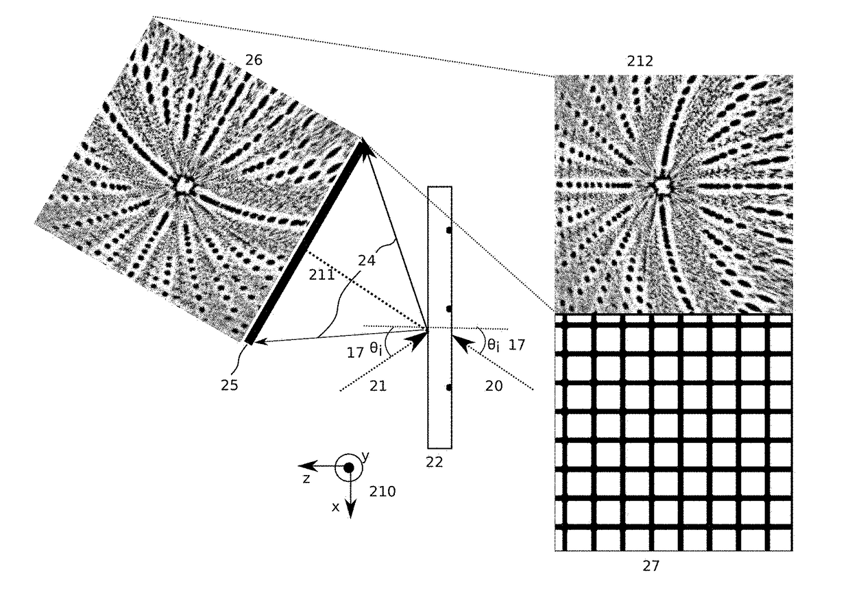
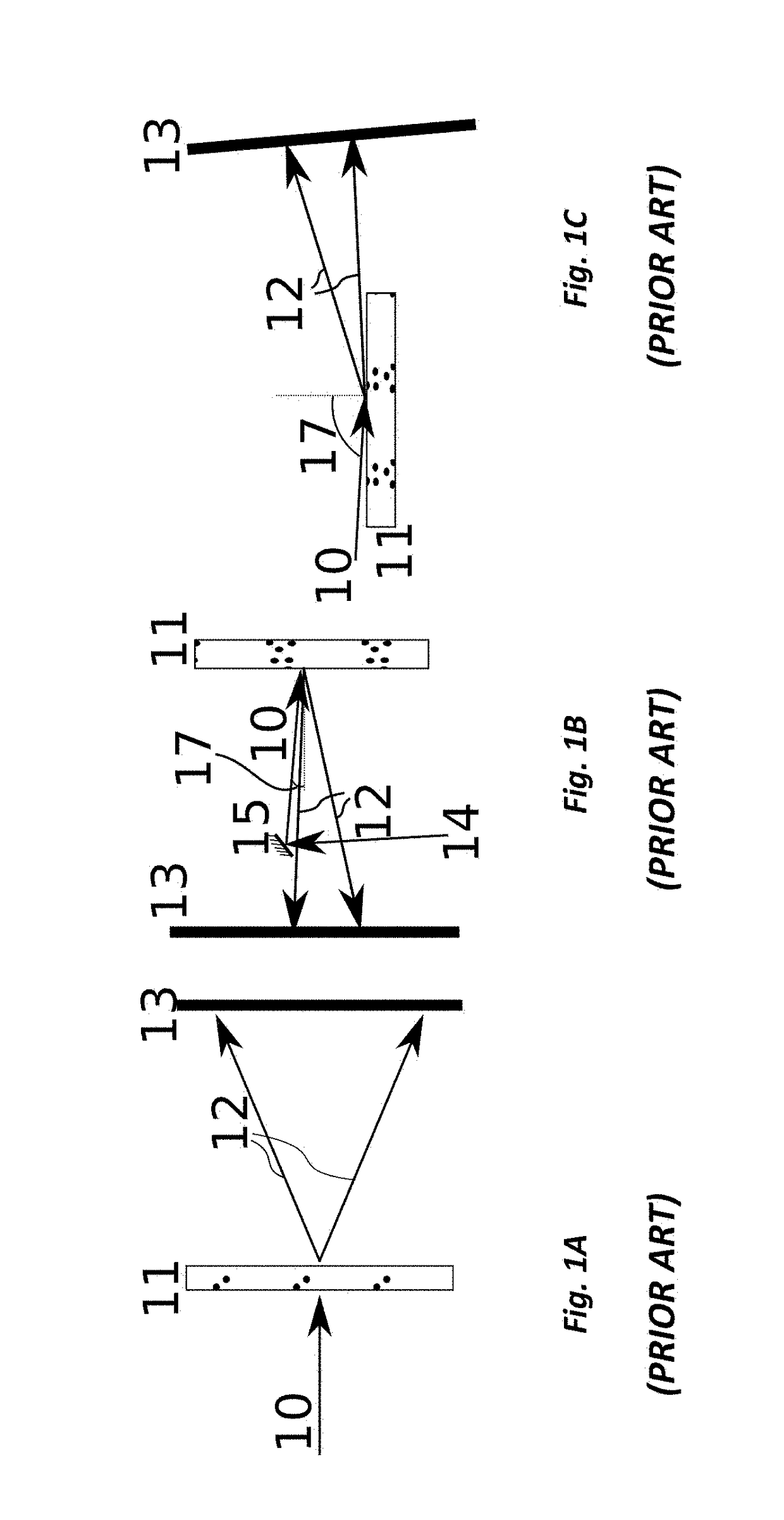
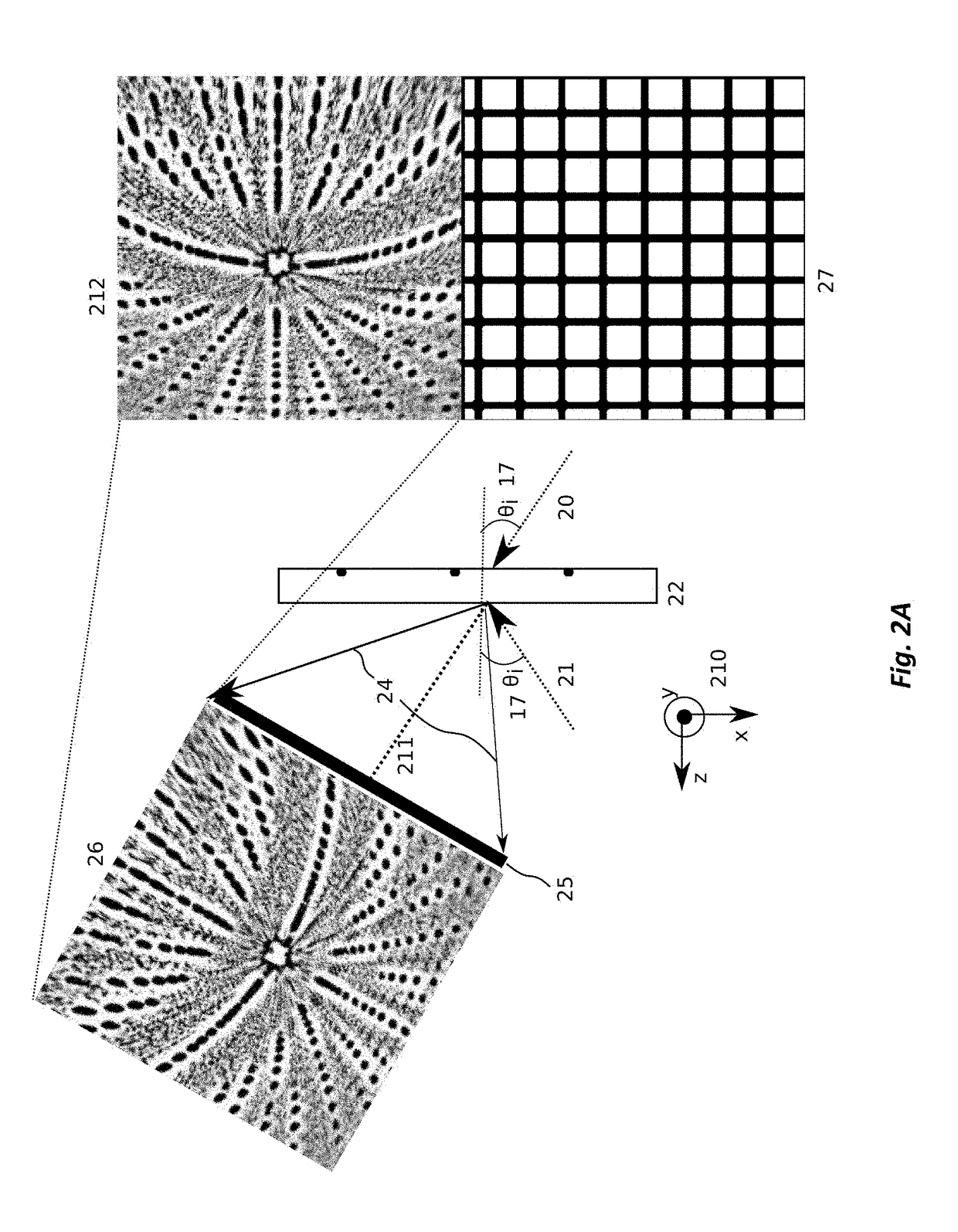
10Incident radiation11Object12Scattering field13Detector14Incident radiation before reflection15Mirror17Angle of incidence or reflection θi20Incident radiation (transmission geometry)21Incident radiation (reflection geometry)22Object24Diffraction intensity25Detector26Diffraction intensity pattern detected27Initial (detector) grid (generally spatially uniform)28Remapped pattern on grid 2929Intermediate grid (chosen to result in uniform spatial frequencygrid 202)34Step of remapping according to the present invention35Slow conventional remapping44Fourier transform magnitude on the detector grid 2748The step of calculating the Fourier transform magnitude202Final grid (generally uniform spatial frequency)204Prior art step of converting from detector grid 27 to a non-uniformspatial frequency grid 302206Step of calculating intermediate grid 29 from final grid 202211The distance from the sample to ...


PUM

PropertyMeasurementUnit
angle of incidence 17θiaaaaaaaaaa
sizeaaaaaaaaaa

Abstract

Apparatus and methods for coherent diffractive imaging with arbitrary angle of illumination incidence utilize a method of fast remapping of a detected diffraction intensity pattern from a detector pixel array (initial grid) to a uniform spatial frequency grid (final grid) chosen to allow for FFT on the remapped pattern. This is accomplished by remapping the initial grid to an intermediate grid chosen to result in a final grid that is linear in spatial frequency. The initial grid is remapped (generally by interpolation) to the intermediate grid that is calculated to correspond to the final grid. In general, the initial grid (x,y) is uniform in space, the intermediate grid ({tilde over (x)},{tilde over (y)}) is non-uniform in spatial frequency, and the final grid ({tilde over (f)}x,{tilde over (f)}y) is uniform in spatial frequency.

Description

BACKGROUND OF THE INVENTION[0001]Field of the Invention[0002]The present invention relates to microscopy and other forms of imaging using coherent light. In particular, the present invention relates to coherent diffractive imaging (CDI) with an arbitrary angle of incidence.[0003]Discussion of Related Art[0004]Coherent diffractive imaging (CDI), for example ptychography, is an emerging technique that enables wavelength- and diffraction-limited imaging. FIG. 1A (Prior Art) shows a conventional 2-dimensional transmission CDI system, where incident radiation 10 illuminates object 11 with a normal incidence, and transmitted scattering field 12 is measured on detector 13.[0005]FIG. 1B (Prior Art) shows a conventional 2-dimensional reflection CDI, where the incident radiation before reflection 14 reflects off of mirror 15 as incident radiation 10 and illuminates object 11 with near-normal incidence (the angle of incidence 17θi is close to 0 degrees).[0006]FIG. 1C shows CDI in a reflection ...

Claims


Application Information

Patent Timeline
Patent Type & Authority Patents(United States)
IPC IPC(8): H04N19/124G02B27/42G02B21/00G03H1/04G01N23/2055G01N23/20G01N23/205G03H1/16G03F1/84G03F7/20G01N21/47G01N21/956H04N19/109G03H1/00
CPCG03H1/0443G02B21/0016G02B27/4205G03F1/84G03F7/70625G03H1/0465G03H1/16G01N23/2055G03H2001/0456G01N21/4788G01N2021/95676G01N2223/611G03H2001/005G03H2001/045G03H2001/0445G01N23/20G21K7/00G01N2223/33G01N2223/345G01N2223/6116G03H1/0866G03H2001/0447G03H2001/0825G03H2240/62G21K2207/005G03H2001/0473G01N21/33G01N21/29G01B11/02
Inventor ZHANG, BOSHENGSEABERG, MATTHEW D.ADAMS, DANIEL E.KAPTEYN, HENRY C.MURNANE, MARGARET M.
Owner UNIV OF COLORADO THE REGENTS OF
Learn More