Catheter spine assembly with closely-spaced bipole microelectrodes

a bipole microelectrode and catheter spine technology, applied in the field of electrophysiology catheters, can solve the problems of difficult to determine, manufacturing and assembling catheter spines with closely and precisely spaced ring electrodes, and difficult to achieve spacing, so as to reduce the detection of undesirable noise.

Active Publication Date: 2018-03-06
BIOSENSE WEBSTER (ISRAEL) LTD
View PDF10 Cites 88 Cited by
  • Summary
  • Abstract
  • Description
  • Claims
  • Application Information

AI Technical Summary

Benefits of technology

[0011]The present invention is directed to an electrophysiologic catheter with a distal electrode assembly carrying very closely-spaced bipole microelectrodes on a plurality of divergent spines that can flexibly spread over tissue surface area for simultaneously detecting signals at multiple locations with minimized detection of undesirable noise, including far-field signals.

Problems solved by technology

Accordingly, even when the catheter is placed in the region of a pulmonary vein, it can be difficult for the electrophysiologist to determine whether the signal is a small, close potential (from the pulmonary vein) or a larger, farther potential (from the atria).
However, manufacturing and assembling catheters with closely and precisely spaced ring electrodes pose many challenges.
However, spacing smaller, especially 0.2 or 0.1 mm spacing is difficult to achieve.
With such smaller spacing, there is the risk of adjacent electrodes coming in contact due to electrode tolerance specification or shifting of electrodes during assembly when medical grade adhesive such as Polyurethane is applied or when medical epoxy is curing.
Such attachment methods often result in an acute angle at which the lead wire must extend to reach the ring electrode which can cause stress leading to detachment or breakage.

Method used


Image

  • Catheter spine assembly with closely-spaced bipole microelectrodes
  • Catheter spine assembly with closely-spaced bipole microelectrodes
  • Catheter spine assembly with closely-spaced bipole microelectrodes

Examples


Embodiment Construction

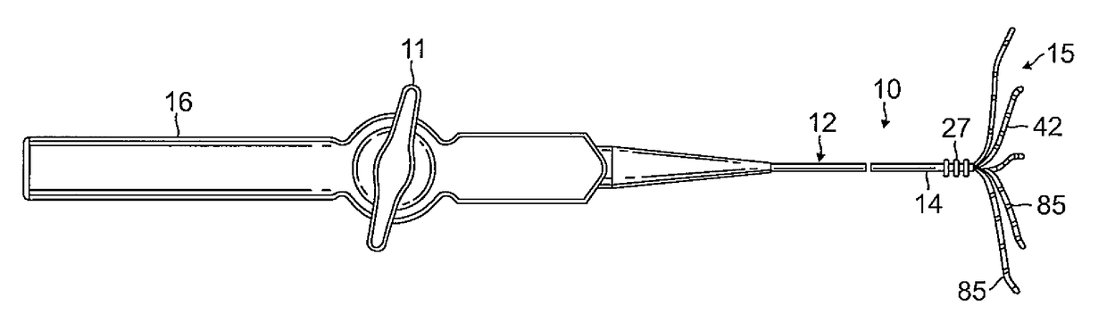
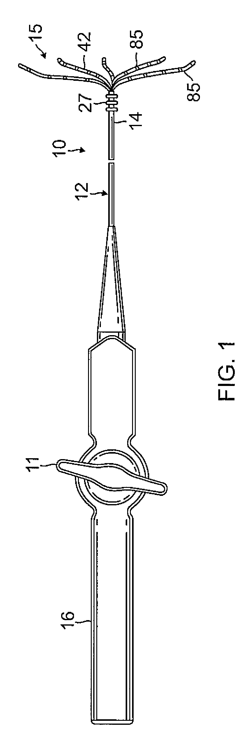
[0038]Referring to FIG. 1, in some embodiment of present invention, a catheter 10 includes a catheter body 12, an intermediate deflection section 14, a distal electrode assembly 15, and a control handle 16 proximal of the catheter body 12. The distal electrode assembly 15 includes a plurality of spines 42, each spine carrying at least one pair of closely-spaced bipole microelectrodes 85, wherein the microelectrodes of a pair has a separation space gap distance therebetween of no greater than about 200 microns.

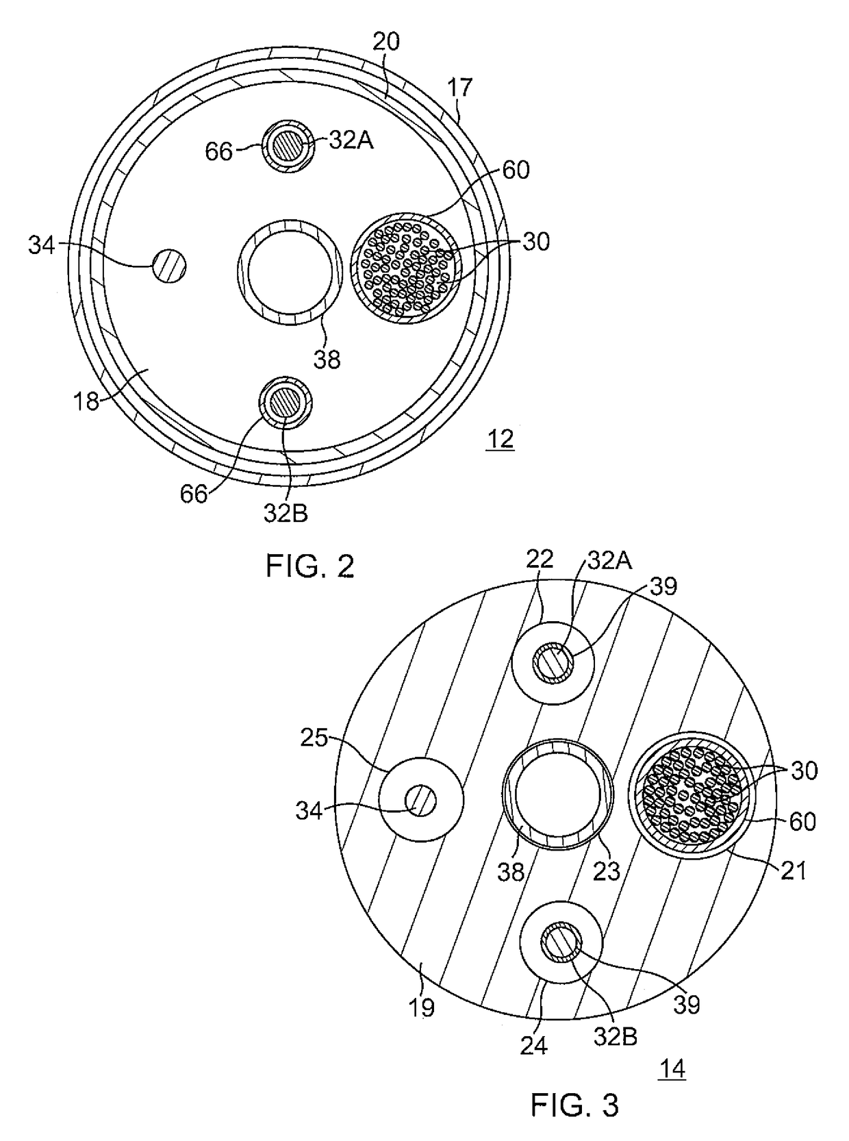
[0039]In some embodiments, the catheter body 12 comprises an elongated tubular construction, having a single, axial or central lumen 18, as shown in FIG. 2. The catheter body 12 is flexible, i.e., bendable, but substantially non-compressible along its length. The catheter body 12 can be of any suitable construction and made of any suitable material. A presently preferred construction comprises an outer wall 17 made of a polyurethane, or PEBAX. The outer wall 17 comprises an imb...


PUM

PropertyMeasurementUnit
space gap distanceaaaaaaaaaa
widthaaaaaaaaaa
widthaaaaaaaaaa

Abstract

An electrophysiologic catheter with a distal electrode assembly carrying very closely-spaced bipole microelectrodes on a plurality of divergent spines that can flexibly spread over tissue surface area minimized detection of undesirable noise, including far-field signals. Each spine has a flexible microelectrode panel having a substrate, at least one pair of microelectrodes, a trace for each microelectrode, and a soldering pad. Adjacent microelectrodes of a bipole pair are separated by a space gap distance ranging between about 50-300 microns. Each microelectrode may have a width of about 200 or 300 microns.

Description

FIELD OF INVENTION[0001]This invention relates to an electrophysiology catheter, in particular, a cardiac electrophysiology catheter with an electrode configuration that provides for more accurate and discrete sensing of fractionated signals.BACKGROUND[0002]Electrode catheters have been in common use in medical practice for many years. They are used to stimulate and map electrical activity in the heart and to ablate sites of aberrant electrical activity.[0003]In use, the electrode catheter is inserted into a major vein or artery, e.g., femoral artery, and then guided into the chamber of the heart which is of concern. Once the catheter is positioned within the heart, the location of aberrant electrical activity within the heart is then located.[0004]One location technique involves an electrophysiological mapping procedure whereby the electrical signals emanating from the conductive endocardial tissues are systematically monitored and a map is created of those signals. By analyzing th...

Claims


Application Information

Patent Timeline
Patent Type & Authority Patents(United States)
IPC IPC(8): A61B5/042A61M25/00A61B18/14
CPCA61B5/0422A61B5/042A61M25/0067A61M25/0054A61B18/1492A61B5/287A61B2018/00148A61B2018/0016A61B2018/00267A61B2018/00351A61B2018/00577A61B2018/1467A61B5/283
Inventor BASU, SHUBHAYUSOLIS, MARIO A.
Owner BIOSENSE WEBSTER (ISRAEL) LTD
Why Eureka
Try Eureka