Fuel valve for injecting gaseous fuel into a combustion chamber of a self-igniting internal combustion engine, engine, method and use

a fuel valve and internal combustion engine technology, applied in the direction of fuel supply apparatus, fuel system, fuel injection apparatus, etc., can solve the problems of difficult to achieve, oil injected in a pilot injection, and reduced emissions

Active Publication Date: 2018-03-06
MAN ENERGY SOLUTIONS FILIAL AF MAN ENERGY SOLUTIONS SE TYSKLAND
View PDF34 Cites 0 Cited by
  • Summary
  • Abstract
  • Description
  • Claims
  • Application Information

AI Technical Summary

Benefits of technology

[0009]On this background, it is an object of the present application to provide a fuel valve for a self-igniting internal combustion engine that overcomes or at least reduces the problems indicated above.
[0011]By a delivery of a finite volume of ignition liquid to chamber in the nozzle a reliable and controlled ignition of the gaseous fuel inside the chamber in the nozzle can be achieved, while using simple means for delivering the ignition liquid and with small consumption of ignition liquid thereby improving emission levels.

Problems solved by technology

However, there are problems associated with using a gaseous fuel in a large low-speed uniflow turbocharged two-stroke internal combustion engine.
One of those problems is the willingness and predictability of gas to self-ignite upon injection into the combustion chamber and both are essential to have under control in a self-igniting engine.
Gaseous fuel operation of these engines is still a relatively recent development and reliability of the operation with gas has not yet reached the level of conventional fuel.
However, the amount of oil injected in a pilot injection should be as small as possible to obtain the desired reduction in emissions.
Dosage of such a small amount with a full size fuel injection system that can also deliver the large amount necessary for operation at full load poses significant technical problems, and is in practice very difficult to achieve and therefore the pilot oil dosage has in existing engines been with a larger quantity per fuel injection event than desirable, especially at medium and low load.
The alternative of an additional small injection system that can handle the small pilot amount is a considerable complication and cost up.
Further, additional small pilot oil injection valves render the top cover of the cylinder even more crowded.

Method used


Image

  • Fuel valve for injecting gaseous fuel into a combustion chamber of a self-igniting internal combustion engine, engine, method and use
  • Fuel valve for injecting gaseous fuel into a combustion chamber of a self-igniting internal combustion engine, engine, method and use
  • Fuel valve for injecting gaseous fuel into a combustion chamber of a self-igniting internal combustion engine, engine, method and use

Examples


Embodiment Construction

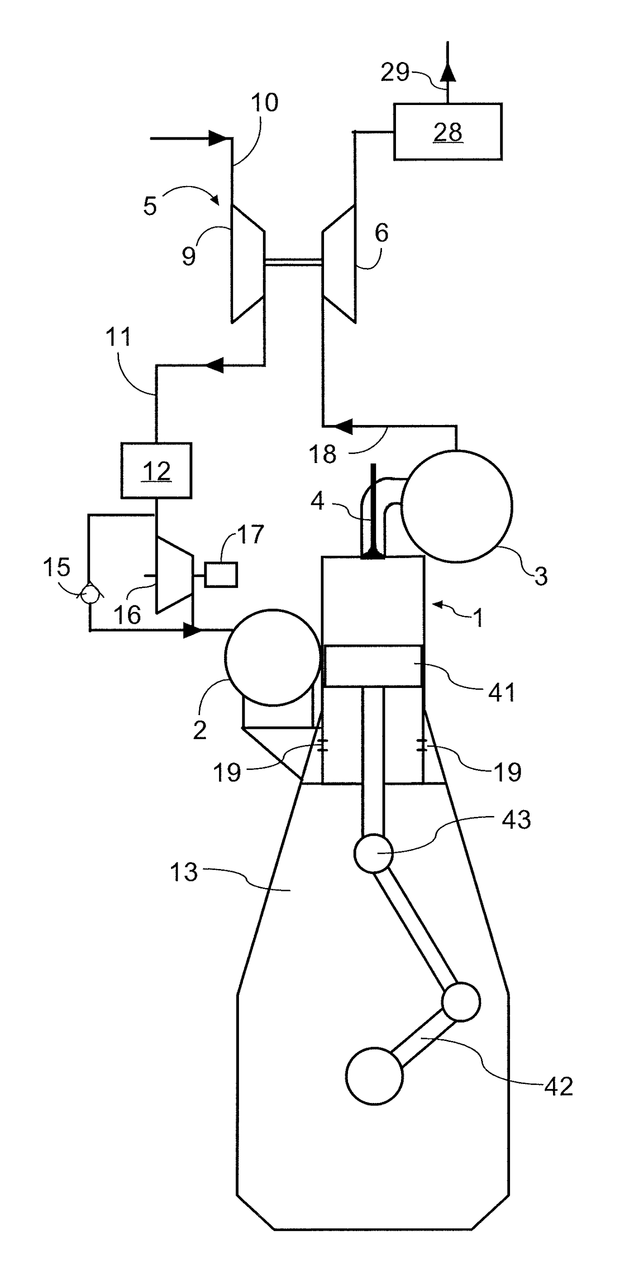
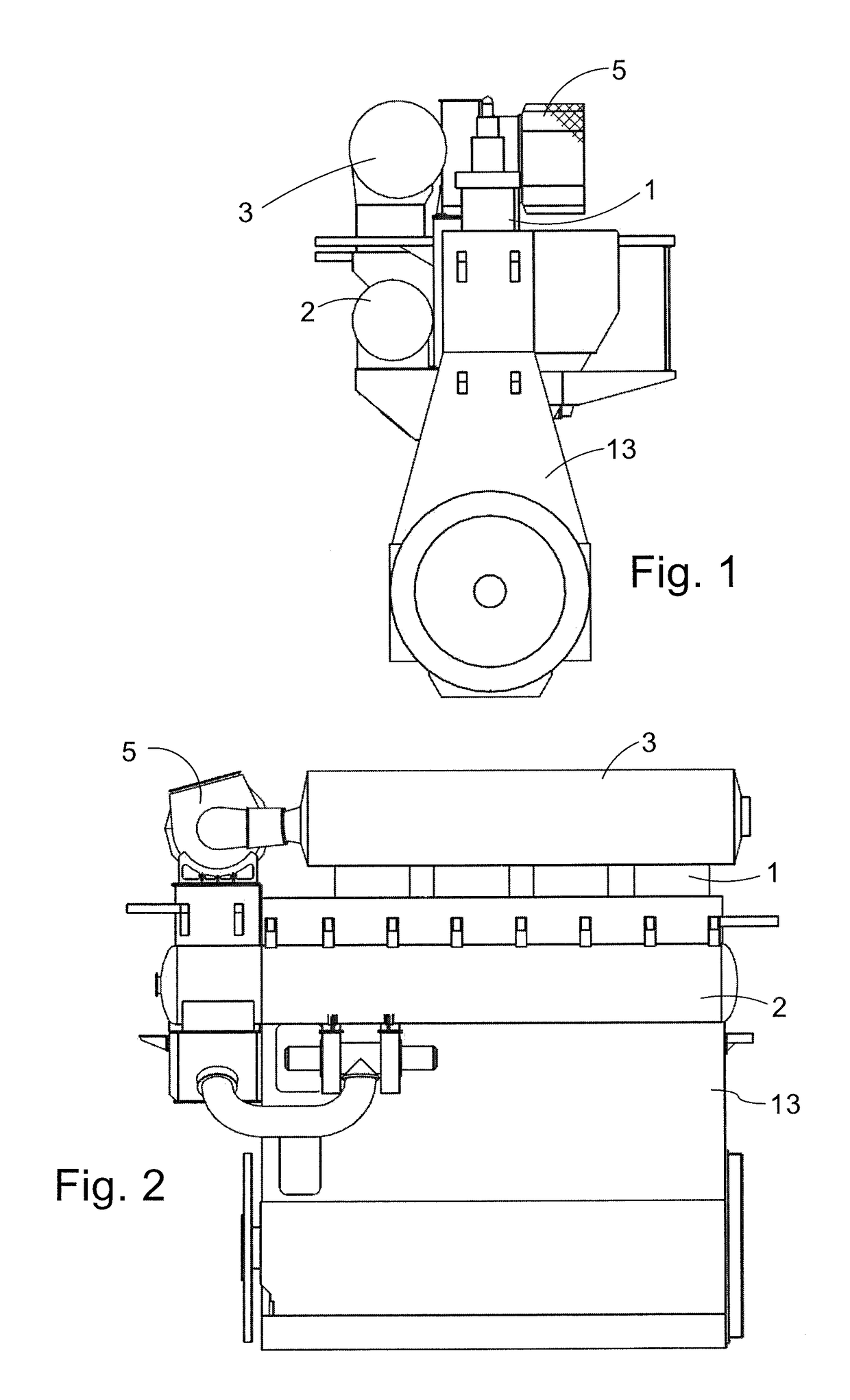
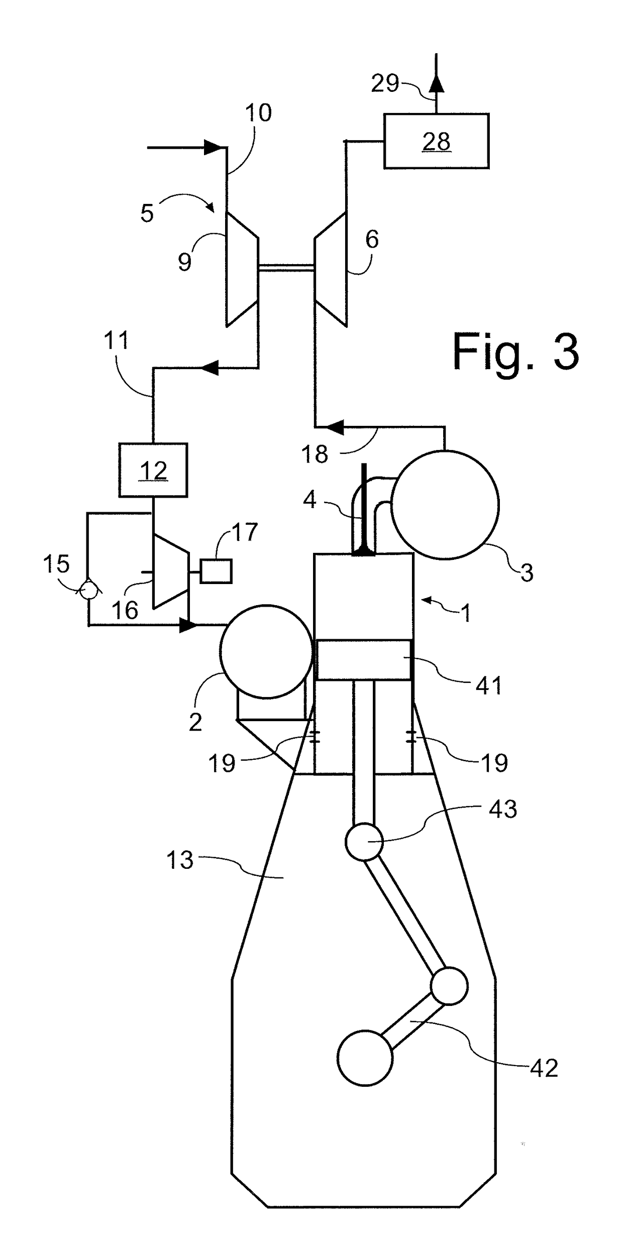
[0056]In the following detailed description, the self-igniting internal combustion engine will be described with reference to a large two-stroke low-speed turbocharged internal combustion (Diesel) engine in the example embodiments. FIGS. 1, 2 and 3 show a large low-speed turbocharged two-stroke diesel engine with a crankshaft 42 and crossheads 43. FIG. 3 shows a diagrammatic representation of a large low-speed turbocharged two-stroke diesel engine with its intake and exhaust systems. In this example embodiment the engine has four cylinders 1 in line. Large low-speed turbocharged two-stroke diesel engines have typically between four and fourteen cylinders in line, carried by an engine frame 13. The engine may e.g. be used as the main engine in an ocean going vessel or as a stationary engine for operating a generator in a power station. The total output of the engine may, for example, range from 1,000 to 110,000 kW. The engine is in this example embodiment a diesel engine of the two-s...


PUM


Abstract

A fuel valve (50) for injecting gaseous fuel into the combustion chamber of a self-igniting internal combustion engine. The fuel valve (50) comprises an elongated fuel valve housing (52) with a rear end and a front end, a nozzle (54) with an elongated nozzle body with a hollow interior that forms a chamber (55) connected to nozzle holes (56), the nozzle (54) being arranged at the front end of the fuel valve housing (52), a gaseous fuel inlet port (53) in the elongated fuel valve housing (52) for connection to a source (60) of high pressure gaseous fuel, an ignition liquid inlet port (78,98) for connection to a source of ignition liquid (57), means (61,69,53,58,61,69) for establishing a timed fluidic connection between the gaseous fuel inlet port and the ignition space (55), and means (61,67,69,76,79,85,98,99) configured for a timed delivery of a finite volume of ignition liquid to the chamber (55) for igniting the gaseous fuel inside the chamber (55).

Description

FIELD OF THE INVENTION[0001]The present invention relates to a gaseous fuel valve for a self-igniting internal combustion engine with a gaseous fuel supply system, in particular to a gaseous fuel valve for a large low-speed uniflow turbocharged two-stroke internal combustion engine with a gaseous fuel supply system.BACKGROUND ART[0002]Large low-speed two-stroke self-igniting (Diesel) engines of the crosshead type are typically used in propulsion systems of large ships or as prime mover in power plants. Very often, these engines are operated with heavy fuel oil or with fuel oil.[0003]Recently, there has been a demand for large two-stroke diesel engines to be able to handle alternative types of fuel, such as gas, coal slurry, petroleum coke and the like, in particular gas.[0004]Gaseous fuels, such as natural gas are relatively clean fuels that result in significantly lower levels of sulfurous components, NOx and CO2 in the exhaust gas when used as fuel for a large low-speed uniflow tu...

Claims


Application Information

Patent Timeline
Patent Type & Authority Patents(United States)
IPC IPC(8): F02M43/04F02M61/04F02M61/10F02M57/02F02M21/02F02D19/10F02D19/06F02B25/04
CPCF02M43/04F02D19/0689F02D19/0694F02D19/10F02M21/0209F02M21/0212F02M21/0266F02M21/0275F02M57/026F02M21/0263Y02T10/36F02B25/04Y02T10/32Y02T10/30F02M43/00F02M47/04F02M47/06F02M61/00F02M61/10F02M61/16F02B43/00F02M61/04
Inventor SJOHOLM, JOHANHULT, JOHAN
Owner MAN ENERGY SOLUTIONS FILIAL AF MAN ENERGY SOLUTIONS SE TYSKLAND
Why Eureka
Try Eureka