Native fluorescence detection methods, devices, and systems for organic compounds

a fluorescence detection and organic compound technology, applied in the field of native fluorescence detection methods, devices, and systems for organic compounds, can solve the problems of insufficient specificity of field instruments in identifying naphthalene specifically, and none of these methods is specific to naphthalene, benzene, toluene,

Active Publication Date: 2018-03-06
PHOTON SYST
View PDF2 Cites 5 Cited by
  • Summary
  • Abstract
  • Description
  • Claims
  • Application Information

AI Technical Summary

Benefits of technology

[0009]It is an object of some embodiments of the invention to provide a compact sensor system for distinguishing one or more selected VOCs while in a vapor state, a solid state, or liquid state.
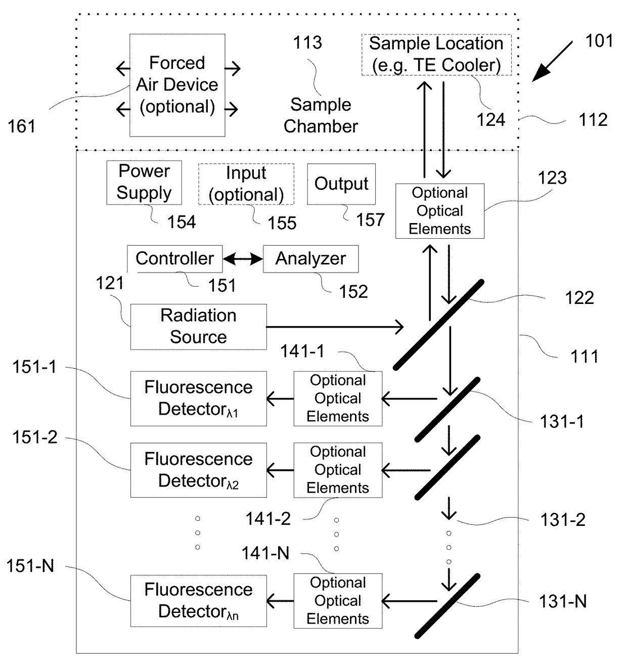
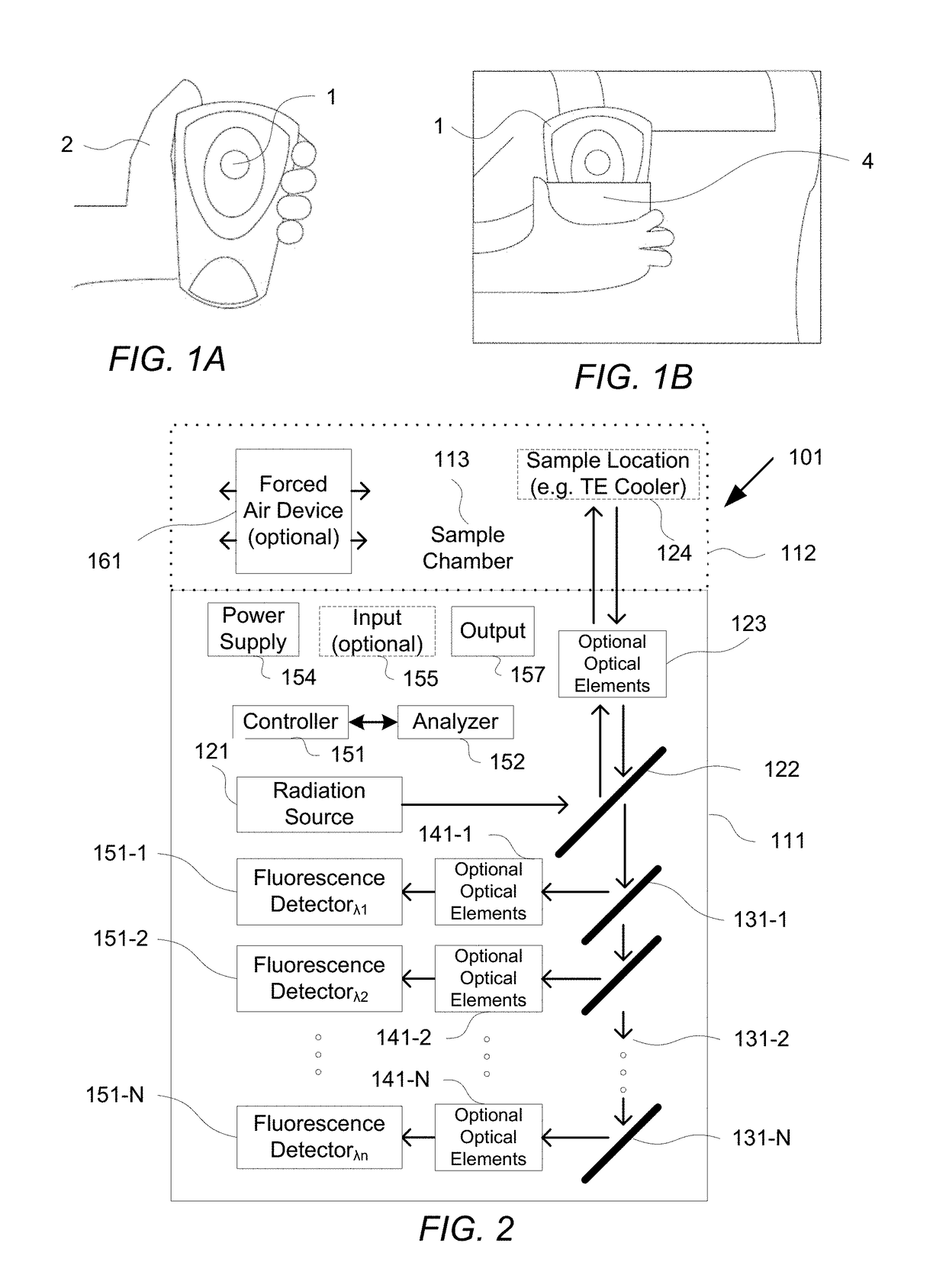
[0010]It is an object of some embodiments of the invention to provide a compact sensor system for distinguishing one or more selected VOCs, while in a vapor, solid, of liquid state, based on detection of native fluorescence stimulated by UV radiation based on one or more of (1) use of rapidly refreshable detection methodology (e.g. new and fresh readings every 5-60 seconds); (2) use of temperature variation elements to cause rapid condensation of VOCs in sample irradiation locations, rapid vaporization of VOCs in sample irradiation locations; (3) use of forced air movement elements to aid in sample location refreshment; (45), use of a small number of discrete spectral bands (e.g. 2-10 bands); (5) use of deep UV wavelengths, e.g. between 185 nm and 300 nm, between 200 nm and 280 nm, or between 220 nm and 250 nm; (6) use of controlled excitation radiation and detection such that detection occurs during excitation while a sample location is at a fixed temperature, is transitioning from a higher to a lower temperature, or is transitioning from a lower to higher temperature, (7) use of controlled excitation radiation and detection such that detection occurs after irradiation is extinguished (e.g. one or more times between 0-100 nanoseconds after extinction of excitation radiation) and while a sample location is at a fixed temperature, is transitioning from a higher to a lower temperature, or is transitioning from a lower to higher temperature, (8) use of data logging and manipulation to provide integrated exposure levels over desired time periods (e.g. hours, work shifts, days, weeks, or the like).
[0012]It is an object of some embodiments of the invention to provide a method for distinguishing one or more selected VOCs, in a vapor, solid, or liquid state, that can be implemented in a compact system based on detecting native fluorescence stimulated by UV radiation based on one or more of (1) use of rapidly refreshable detection methodology (e.g. new and fresh readings every 5-60 seconds); (2) use of temperature variation elements to cause rapid condensation of VOCs in sample irradiation locations, rapid vaporization of VOCs in sample irradiation locations; (3) use of forced air movement elements to aid in sample location refreshment; (4), use of a small number of discrete spectral bands (e.g. 2-10 bands); (5) use of deep UV wavelengths, e.g. between 185 nm and 300 nm, between 200 nm and 280 nm, or between 220 nm and 250 nm; (6) use of controlled excitation radiation and detection such that detection occurs during excitation while a sample location is at a fixed temperature, is transitioning from a higher to a lower temperature, or is transitioning from a lower to higher temperature, (7) use of controlled excitation radiation and detection such that detection occurs after irradiation is extinguished (e.g. one or more times between 0-100 nanoseconds after extinction of excitation radiation) and while a sample location is at a fixed temperature, is transitioning from a higher to a lower temperature, or is transitioning from a lower to higher temperature, (8) use of data logging and manipulation to provide integrated exposure levels over desired time periods (e.g. hours, work shifts, days, weeks, or the like).
[0013]It is an object of some embodiments to provide improved detection and analysis methods, devices, or systems for detecting and evaluating organic compounds of interest that may be located on surfaces or within an atmosphere within a sample chamber forming part of a device or as solids, liquids or gases external to the device as detected by exposing the environment around the device to selected excitation radiation and detecting any returning emission radiation (e.g. fluorescence) from the environment to one or more detectors located within the device. The improved methods, devices and systems may provide detection of materials located outside a device housing such as vapors in the atmosphere around the device, solid surfaces within an environment of interest, or even within liquid, paste, slurry, powder, or other flowable or spreadable materials located in the environment of interest. Such surfaces may include, for example, floors, walls, sinks, seats, tables, utensils, tools, surfaces of equipment such as vehicles, food processing equipment, pharmaceutical processing equipment, containers for handling various liquid, paste, or powder materials and particularly if residual amounts of one type of material handled or carried in the containers can contaminate a subsequent material to be handled or carried or where contaminates effecting a first carried or handled material can negatively impact a subsequently handled or carried material. Such materials, that may benefit from improved detection and analysis devices, methods, and systems, may for example include flowable food substances (e.g. milk, yogurt, dough, butter, cheese, fruit juices, peanut butter, and the like), precursor food substances (e.g. bacterial colonies), pharmaceuticals, pharmaceutical precursors, chemical mixtures, water, drinkable liquids, and the like. Other materials include by-products of food, pharmaceutical, and industrial cleaning processes to either ensure completion of removal of desired contaminates or other materials (e.g. by their absence from a waste stream), or to ensure that by-products themselves do not contain dangerous or excessive amounts or concentrations of selected materials.

Problems solved by technology

None of these methods is specific to naphthalene, benzene, toluene, xylene, and several other hazardous VOCs.
Because of the traditional size, weight, and power consumption of laboratory instruments, they are not suitable for significant miniaturization, and present field instruments have inadequate specificity in identifying naphthalene specifically.

Method used


Image

  • Native fluorescence detection methods, devices, and systems for organic compounds
  • Native fluorescence detection methods, devices, and systems for organic compounds
  • Native fluorescence detection methods, devices, and systems for organic compounds

Examples


Embodiment Construction

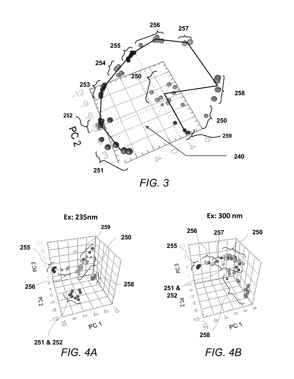
[0046]Methods and sensor systems of embodiments of the invention based on deep UV (e.g. having a relative narrow band of wavelengths above 185 nm but less than 200 nm, above 200 nm but less than 280 nm, or above 220 nm but less than 250 nm) excited native fluorescence have demonstrated the ability to clearly distinguish between standard jet fuels which contain naphthalene (e.g. MAPLLC Aviation Turbine Fuel Jet A (04posf4658) fuel with about 3% naphthalene compounds) and new, synthetic fuels (e.g. S-8 Synthetic Jet Fuel (06posf5018fuel)) which contains essentially no naphthalene. Various embodiments have demonstrated sufficient sensitivity that trace amounts of naphthalene could be detected in the S-8 jet fuel (without naphthalene) but which was stored in containers where Jet A was previously stored. The embodiments have also demonstrated that naphthalene can be distinguished from other volatile organic compounds (VOCs).

[0047]Some embodiments have achieved continuous detection of nap...


PUM

PropertyMeasurementUnit
wavelengthaaaaaaaaaa
heightsaaaaaaaaaa
heightsaaaaaaaaaa

Abstract

Naphthalene, benzene, toluene, xylene, and other volatile organic compounds VOCs have been identified as serious health hazards. Embodiments of the invention are directed to methods and apparatus for near-real-time in-situ detection and accumulated dose measurement of exposure to naphthalene vapor and other hazardous gaseous VOCs. The methods and apparatus employ excitation of fluorophors native or endogenous to compounds of interest using light sources emitting in the ultraviolet below 300 nm and measurement of native fluorescence emissions in distinct wavebands above the excitation wavelength. The apparatus of some embodiments are cell-phone-sized sensor / dosimeter “badges” to be worn by personnel potentially exposed to hazardous VOCs. The badge sensor of some embodiments provides both real time detection and data logging of exposure to naphthalene or other VOCs of interest from which both instantaneous and accumulated dose can be determined.

Description

RELATED APPLICATIONS[0001]This application is a continuation of U.S. patent application Ser. No. 14 / 313,994, filed Jun. 24, 2014. The '994 application is a continuation-in-part of U.S. patent application Ser. No. 12 / 628,205, filed Nov. 30, 2009, now U.S. Pat. No. 8,759,791. The '205 application claims benefit of U.S. Patent Application No. 61 / 118,591, filed Nov. 28, 2008 and is a continuation-in-part of U.S. patent application Ser. No. 12 / 545,772, filed Aug. 21, 2009, now U.S. Pat. No. 8,395,770, which in turn is a continuation-in-part of U.S. patent application Ser. No. 12 / 399,743, filed Mar. 6, 2009, now U.S. Pat. No. 7,800,753, which in turn is a continuation of U.S. patent application Ser. No. 11 / 245,486, filed Oct. 5, 2005, now U.S. Pat. No. 7,525,653, which in turn claims benefit of U.S. Provisional Application No. 60 / 616,269, filed Oct. 5, 2004. Each of these applications is incorporated herein by reference as if set forth in full herein.U.S. GOVERNMENT RIGHTS[0002]One or mor...

Claims


Application Information

Patent Timeline
Patent Type & Authority Patents(United States)
IPC IPC(8): G01N21/64
CPCG01N21/64G01N2201/0612G01N2201/062G01J3/10G01J3/36G01J3/44G01N27/44721G01N21/65G01N2021/6421G01N2021/6471G01N33/0047G01N21/6486G01N21/8806G01N2201/06113G01N2201/126
Inventor HUG, WILLIAM F.BHARTIA, ROHITREID, RAY D.LANE, ARTHUR L.
Owner PHOTON SYST
Why Eureka
Try Eureka