Method for depositing layer

a layer and depositing technology, applied in the direction of metal material coating process, coating, pressure inorganic powder coating, etc., can solve the problem of increasing and achieve the effect of reducing the number of heat treatment and reducing the cost of layer deposition

Active Publication Date: 2018-04-03
MITSUBISHI HEAVY IND LTD
View PDF10 Cites 0 Cited by
  • Summary
  • Abstract
  • Description
  • Claims
  • Application Information

AI Technical Summary

Benefits of technology

[0012]The inventors of this application have recognized the following points. As described above, in order to form the thick layer using the cold spray process, it is necessary to perform the heat treatment during performing the layer deposition method. However, as the number of the heat treatment increases, the layer deposition time also increases as a whole. It is not only because the heat treatment itself requires a certain amount of time, but also because it is necessary to stop a cold spray apparatus every time of heat treating and it is necessary to restart and adjust the cold spray apparatus every time of restarting the layer deposition process. That is, as the number of the heat treatment increases, layer deposition costs increase. Therefore, the fewer the number of the heat treatment (the unit deposition process), the better.
[0013]One object of the present invention is to provide a technique with which it is possible to reduce the number of the heat treatment (the unit deposition process) in depositing a thick layer using cold spraying.
[0016]According to the present invention, it is possible to reduce the number of the heat treatment (the unit deposition process) in depositing the thick layer using cold spraying. As a result, layer deposition costs can be reduced.

Problems solved by technology

It is not only because the heat treatment itself requires a certain amount of time, but also because it is necessary to stop a cold spray apparatus every time of heat treating and it is necessary to restart and adjust the cold spray apparatus every time of restarting the layer deposition process.
That is, as the number of the heat treatment increases, layer deposition costs increase.

Method used


Image

  • Method for depositing layer
  • Method for depositing layer
  • Method for depositing layer

Examples


first embodiment

1. First Embodiment

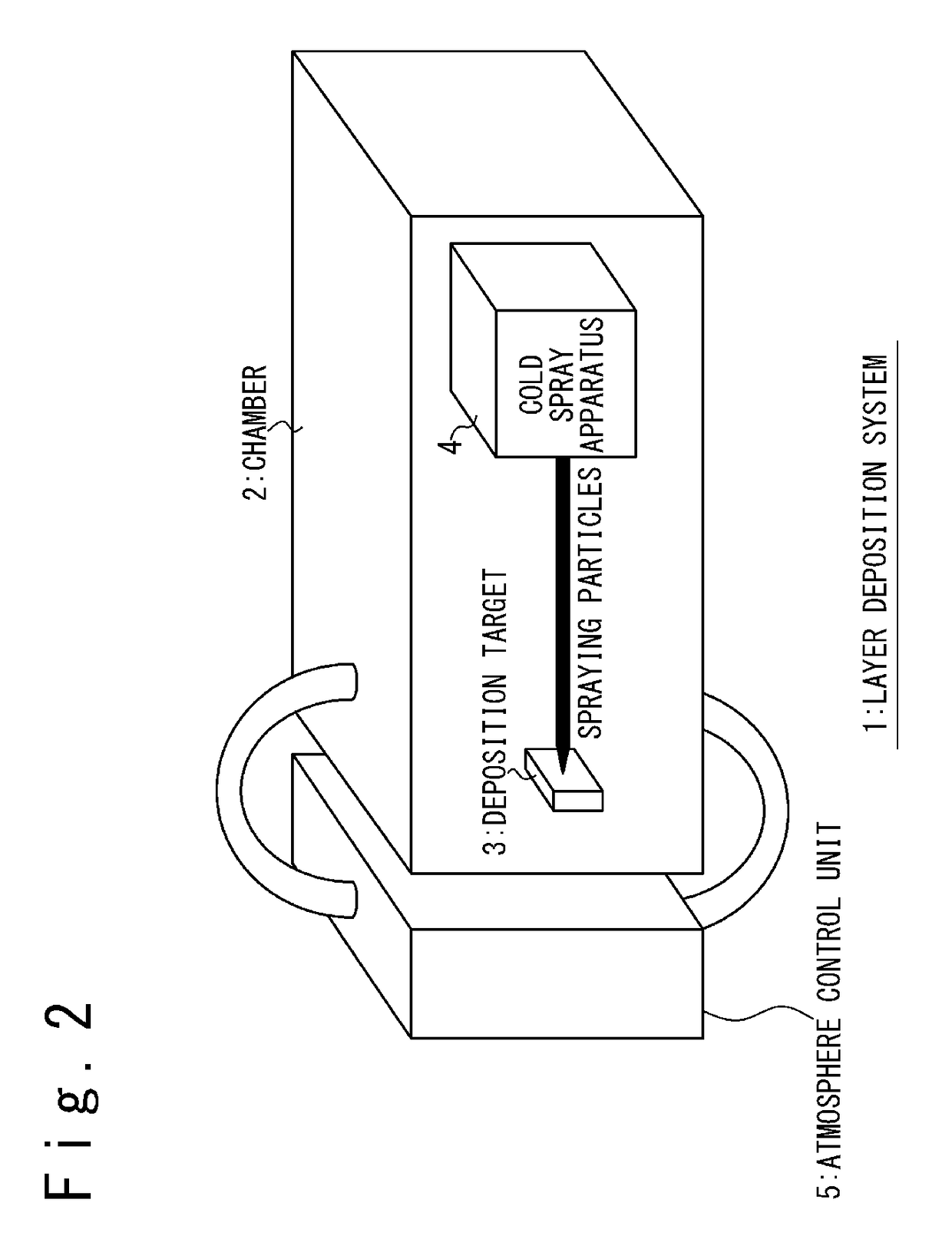
[0030]FIG. 2 schematically indicates the configuration of the layer deposition system 1 according to the first embodiment. The layer deposition system 1 includes a chamber 2, a cold spray apparatus 4, and an atmosphere control unit 5. In the chamber 2 (layer deposition chamber), a deposition target 3 is arranged. The cold spray apparatus 4 is arranged so that it is possible to perform the layer deposition on the deposition target 3 using the cold spray process.

[0031]The atmosphere control unit 5 is arranged for controlling an atmosphere in the chamber 2. In the first embodiment, the atmosphere control unit 5 is a gas supply apparatus for supplying “non-oxidizing gas” into the chamber 2. The non-oxidizing gas is, for example, inert gas such as Ar and He, and nitrogen N2.

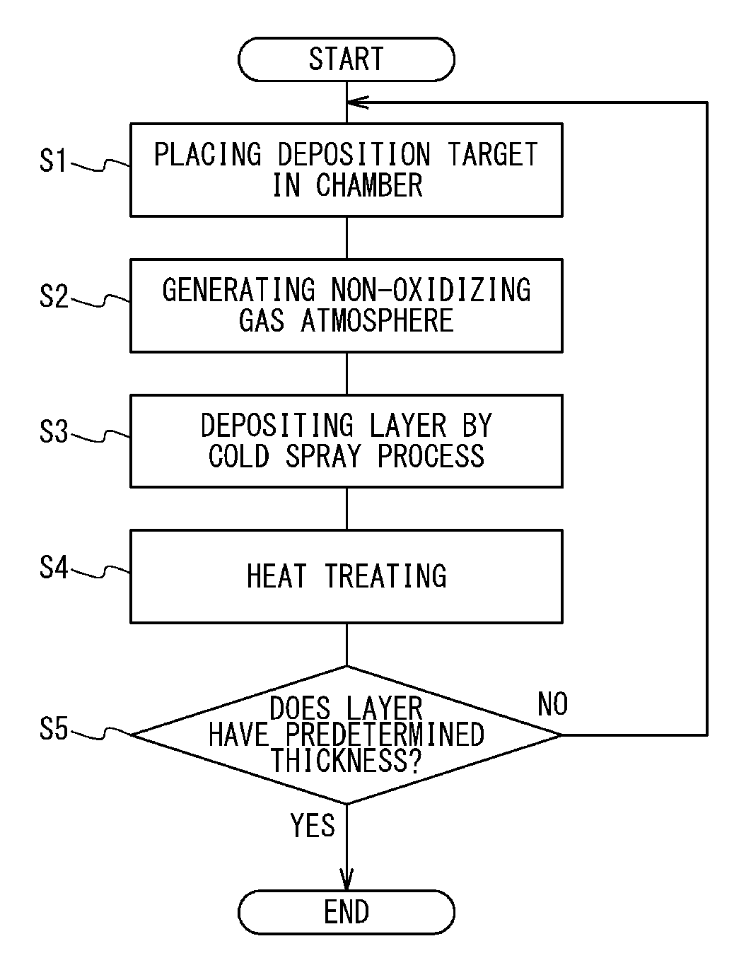
[0032]FIG. 3 is the flowchart for indicating the layer deposition method according to the first embodiment. Referring to FIG. 2 and FIG. 3, the layer deposition method according to the first embodim...

second embodiment

2. Second Embodiment

[0050]According to the above-described first embodiment, the atmosphere in the chamber 2 is set to the non-oxidizing gas atmosphere. However, as long as the oxidation is suppressed, the atmosphere is not limited thereto. In the second embodiment, in place of the non-oxidizing gas atmosphere, a vacuum atmosphere is used. In this case, the atmosphere control unit 5 is a pressure reducing unit for making a state in the chamber a vacuum state. The vacuum state is, for example, a state in which the pressure is 1×10⁻³ Pa or less.

[0051]FIG. 5 is the flowchart for indicating the layer deposition method according to the second embodiment. In the second embodiment, instead of above-described Step S2, Step S2′ is performed. In Step S2′, the atmosphere control unit 5 is activated to set the atmosphere in the chamber 2 to the vacuum atmosphere. The rest is the same as the first embodiment.

[0052]According to the second embodiment, the same effect can be obtained as the first e...

third embodiment

3. Third Embodiment

[0053]FIG. 6 schematically indicates the configuration of the layer deposition system 1 according to the third embodiment. The layer deposition system 1 includes the cold spray apparatus 4 and a heater 6. The heater 6 is disposed to be able to heat the deposition target 3, and typically is arranged so as to contact the deposition target 3. The cold spray apparatus 4 is disposed so as to be able to perform the layer deposition on the deposition target 3 by the cold spray process.

[0054]FIG. 7 is the flowchart for indicating the layer deposition method according to the third embodiment. Referring to FIG. 6 and FIG. 7, the layer deposition method according to the third embodiment will be explained. Note that explanations that are duplicative of those provided with respect to the first embodiment are appropriately omitted.

Step S3′:

[0055]The heater 6 is activated, and heats the deposition target 3. As a result, the temperature of the deposition target 3 becomes higher t...


PUM

PropertyMeasurementUnit
thicknessaaaaaaaaaa
thickaaaaaaaaaa
thicknessaaaaaaaaaa

Abstract

A method for depositing a layer includes repeatedly performing a unit deposition process until the layer on a deposition target reaches a predetermined thickness. The unit deposition process includes (A) placing the deposition target in a chamber, (B) providing a non-oxidizing gas atmosphere or a vacuum atmosphere in the chamber, (C) depositing the layer on the deposition target by a cold spray process in the non-oxidizing gas atmosphere or the vacuum atmosphere, and (D) heat treating the deposition target after the depositing.

Description

CROSS-REFERENCE TO RELATED APPLICATION[0001]This application claims priority from Japanese Patent Application No. JP 2013-030378 filed on Feb. 19, 2013, the disclosure of which is hereby incorporated by reference herein in its entirety.TECHNICAL FIELD[0002]The present invention relates to a method for depositing a layer using cold spraying.BACKGROUND ART[0003]There is a case in which it is necessary to form a thick layer on a base member to manufacture a structure. Such a structure is, for example, a combustion chamber of a space rocket engine or an aerospace rocket engine. When the combustion chamber of the rocket engine is manufactured, it is necessary, for example, to form a copper layer having a thickness of 10 mm or more on the base member formed of copper.[0004]One method for forming such a thick metal layer is “electroplating”. However, a layer growth rate using electroplating is extremely slow. For example, it takes several months to reach a target layer thickness of about 1...

Claims


Application Information

Patent Timeline
Patent Type & Authority Patents(United States)
IPC IPC(8): C23C4/06C23C4/12C23C24/04C23C4/18
CPCC23C4/137C23C24/04C23C4/18C23C4/06
Inventor SAITO, MAKOTOHIRAMATSU, NORIYUKIFUKUSHIMA, AKIRA
Owner MITSUBISHI HEAVY IND LTD
Why Eureka
Try Eureka