Signal equalisation

a signal equalization and signal technology, applied in the direction of transmitter/receiver shaping network, transmission system, survey, etc., can solve the problems of limiting hardware computational resources to low speed processors, difficult communication, present noise, etc., to increase immunity to noise and increase immunity

Active Publication Date: 2018-04-10
RAPTOR DATA LTD
View PDF7 Cites 2 Cited by
  • Summary
  • Abstract
  • Description
  • Claims
  • Application Information

AI Technical Summary

Benefits of technology

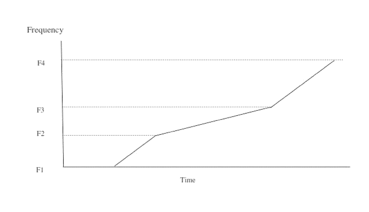
[0021]By locally modifying the frequency structure of chirps, it is possible to enhance the gain in the sections of the chirp corresponding to frequencies where attenuation is most prevalent while reducing the power applied over the entire operating range of the chip communications channel. This balance is achieved by implementing local extension in the time bandwidth product (TB product) of the chirp pulse in the attenuated frequency bands.
[0026]The method thus delivers a pulse design that balances noise immunity with power consumption in an elegant and reliable manner. The method is especially applicable to an acoustic telemetry channel, such as that used for low-data rate communications between downhole equipment and head-end equipment in the field of drill-based hydrocarbon exploration.
[0027]By modifying the frequency structure of chirps, it is possible to enhance the noise immunity properties of the chirp for those frequencies where noise is experienced while reducing the power applied over the entire operating range of the chip communications channel. This balance is achieved by implementing local extension in the time bandwidth product (TB product) of the chirp pulse in the noisy frequency bands.
[0028]The local extension of the TB product means that the signal in the extended frequency range is “pre-emphasised”. The pre-emphasis in turn reduces the effective bandwidth of the resulting waveform and increases that width of the pulse when it is decoded. When counteracting noise, the method then compensates for this pre-emphasis by applying a complementary “de-emphasis” function (i.e. a signal equalisation or “correlator” function).
[0029]The method therefore facilitates signal equalization against noise by modifying chirp pulses to reduce the influence of noise at certain frequency ranges, while ensuring that power need not be applied at frequency ranges where noise is comparatively low.

Problems solved by technology

One particularly challenging scenario relates to acoustic communications “downhole” in the field of drill-based hydrocarbon exploration and extraction.
Downhole conditions are hostile with unstable, difficult communication conditions and high temperatures.
The high temperature environment, such as a deep well, restricts hardware computational resources to low speed processors with small amounts of on-board memory.
One of the roots of instability in such communication channels is the present of noise.
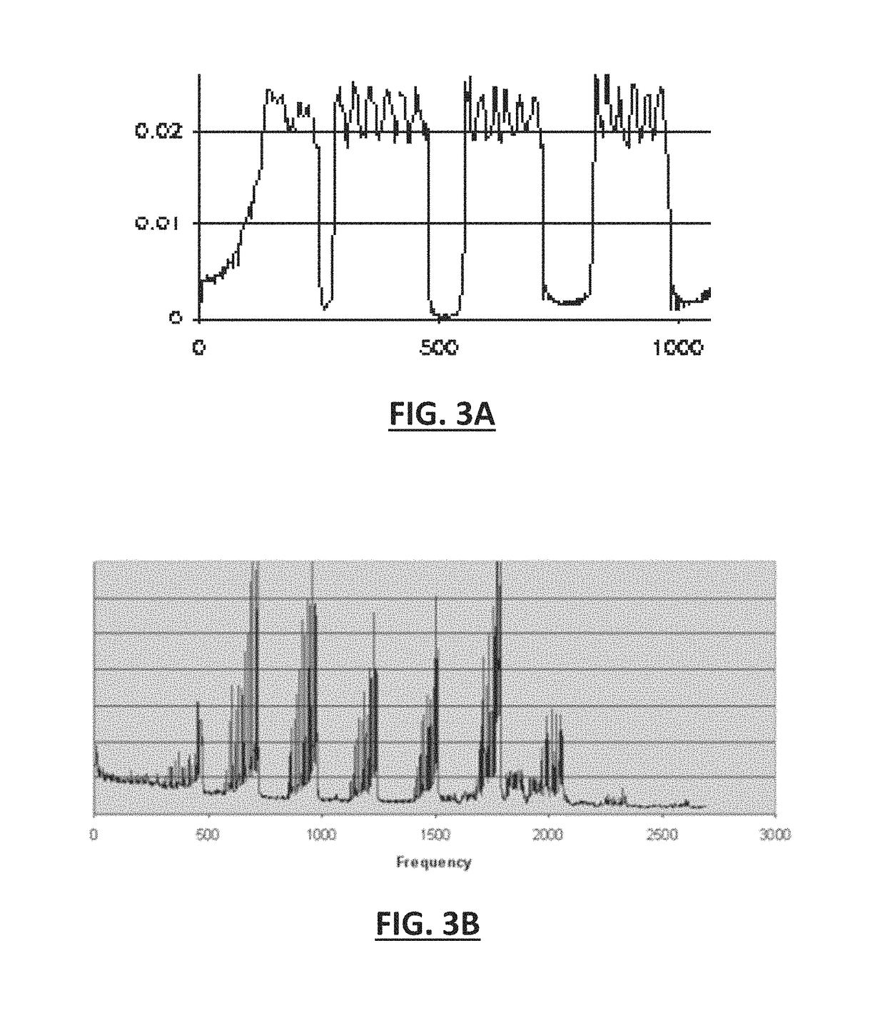
“In well” communication by means of acoustic pulse transmission and reception (i.e. acoustic telemetry) along a drillstring is severely limited by the dynamic and non-stationary nature of the channel both in terms of noise and channel transfer function.
One main issue in downhole communications is to ensure that signals sent by a first unit (i.e. transceiver node) in an acoustic telemetry system reach and are detected by a second unit in that system, even when the transmission lies well inside noise (i.e. having an amplitude comparable to noise in the transmission medium).
The presence of noise in current acoustic telemetry systems means that relays are required to boost the signal beyond a maximum of 2,500 m in a vertical deployment and 950 m in a horizontal deployment.
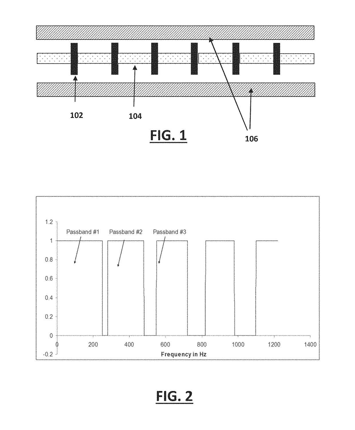
Typically passbands having the lowest frequencies are considered to contain unacceptably high levels of noise and are therefore thought not to be viable for the purpose of downhole communications.
In addition, these known systems rarely use more than one passband, again limiting the performance and flexibility of the device.
In summary, current systems have limited their technical solution in order to gain reliability but have sacrificed performance, flexibility, and (ironically) reliability.
Known techniques do little to address noise immunity and typically require pumping / drilling to stop—low frequency passbands are avoided due to high intrinsic background noise.
The pre-emphasis in turn reduces the effective bandwidth of the resulting waveform and increases that width of the pulse when it is decoded.

Method used


Image

  • Signal equalisation
  • Signal equalisation
  • Signal equalisation

Examples


Embodiment Construction

[0068]The detailed description set forth below in connection with the appended drawings is intended as a description of presently preferred embodiments of the disclosure, and is not intended to represent the only forms in which the present disclosure may be practised. It is to be understood that the same or equivalent functions may be accomplished by different embodiments that are intended to be encompassed within the spirit and scope of the invention. In the drawings, like numerals are used to indicate like elements throughout. Furthermore, terms such as “comprises”, “comprising”, “contains” or any other variation thereof, are intended to cover a non-exclusive inclusion, such that module, circuit, device components, structures and method steps that comprises a list of elements or steps does not include only those elements but may include other elements or steps not expressly listed or inherent to such module, circuit, device components or steps. An element or step proceeded by “com...


PUM


Abstract

Generated chirp pulses are modified so that they have an increased time bandwidth product to compensate for noise and / or attenuation in a communication channel. In certain circumstances, the modification alone may be inefficient so a counterbalancing modification may be applied at the receiver.

Description

BACKGROUND[0001]Technical Field[0002]The present invention relates generally to the control of noise in communication channels. More specifically, the present invention relates to the control of noise in communication channels that use broadband chirps.[0003]Description of Related Art[0004]Broadband chirp signals have been found useful in various communication scenarios. One particularly challenging scenario relates to acoustic communications “downhole” in the field of drill-based hydrocarbon exploration and extraction.[0005]Downhole conditions are hostile with unstable, difficult communication conditions and high temperatures. The high temperature environment, such as a deep well, restricts hardware computational resources to low speed processors with small amounts of on-board memory. Unstable communication channels (whether electromagnetic, acoustic or wired) or the need to prioritize data processing leads to the requirement for flexibility in managing resources as conditions chan...

Claims


Application Information

Patent Timeline
Patent Type & Authority Patents(United States)
IPC IPC(8): H04B1/69H04L25/03H04B1/713H04B1/707G08C23/02
CPCH04B1/69H04L25/03834G08C23/02H04B2001/6912E21B47/14H04B11/00H04L27/103
Inventor MACLEAN, COLINCOWIE, GORDON
Owner RAPTOR DATA LTD
Why Eureka
Try Eureka