Enhancement of claus tail gas treatment with membrane and reducing step

a technology of claus tail gas treatment and membrane, which is applied in the direction of sulfur preparation/purification, hydrogen sulfide, and separation processes, etc., can solve the problems of significant capital cost to the claus treatment unit, catalyst bed plugging or deactivating, and reaction furnaces that can destroy contaminants such as hydrocarbons, and achieve the effect of minimizing sulfur dioxide emissions and improving sulfur recovery

Active Publication Date: 2018-04-17
SAUDI ARABIAN OIL CO
View PDF26 Cites 8 Cited by
  • Summary
  • Abstract
  • Description
  • Claims
  • Application Information

AI Technical Summary

Benefits of technology

[0013]This invention relates to a system and method for improving sulfur recovery from a sulfur recovery unit. More specifically, this invention provides a system and method for treating acid gas streams and minimizing sulfur dioxide emissions therefrom.

Problems solved by technology

With more stringent fuel regulations and increasing environmental concerns, together with the need to process sourer crude oils and natural gases, sulfur recovery has become one of the leading issues in emission reduction.
In addition, the reaction furnace can destroy contaminants, such as hydrocarbons, that are present in the feed gas stream.
Such contaminants pose problems for the catalytic reactors through the development of carbon-sulfur compounds that can lead to plugging or deactivation of the catalyst beds.
Currently available tail gas treatment units can be effective at achieving up to 99.2% recovery, but can add significant capital cost to the Claus treatment unit, often on the same order of magnitude as the Claus unit itself.
While the Scot process can reach 99.9% sulfur recovery, the added cost and unit complexity makes this process unfeasible when the Claus feed is not highly concentrated with hydrogen sulfide, e.g., unless greater than 55%.
In addition to increase operating and capital costs, these technologies can require significant physical footprint for the various process vessels, columns, pumps, and storage vessels necessary for operation.

Method used


Image

  • Enhancement of claus tail gas treatment with membrane and reducing step
  • Enhancement of claus tail gas treatment with membrane and reducing step
  • Enhancement of claus tail gas treatment with membrane and reducing step

Examples


example 1

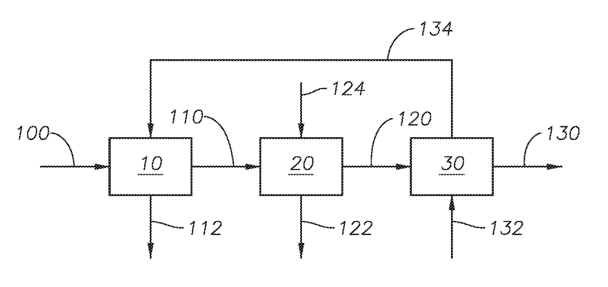
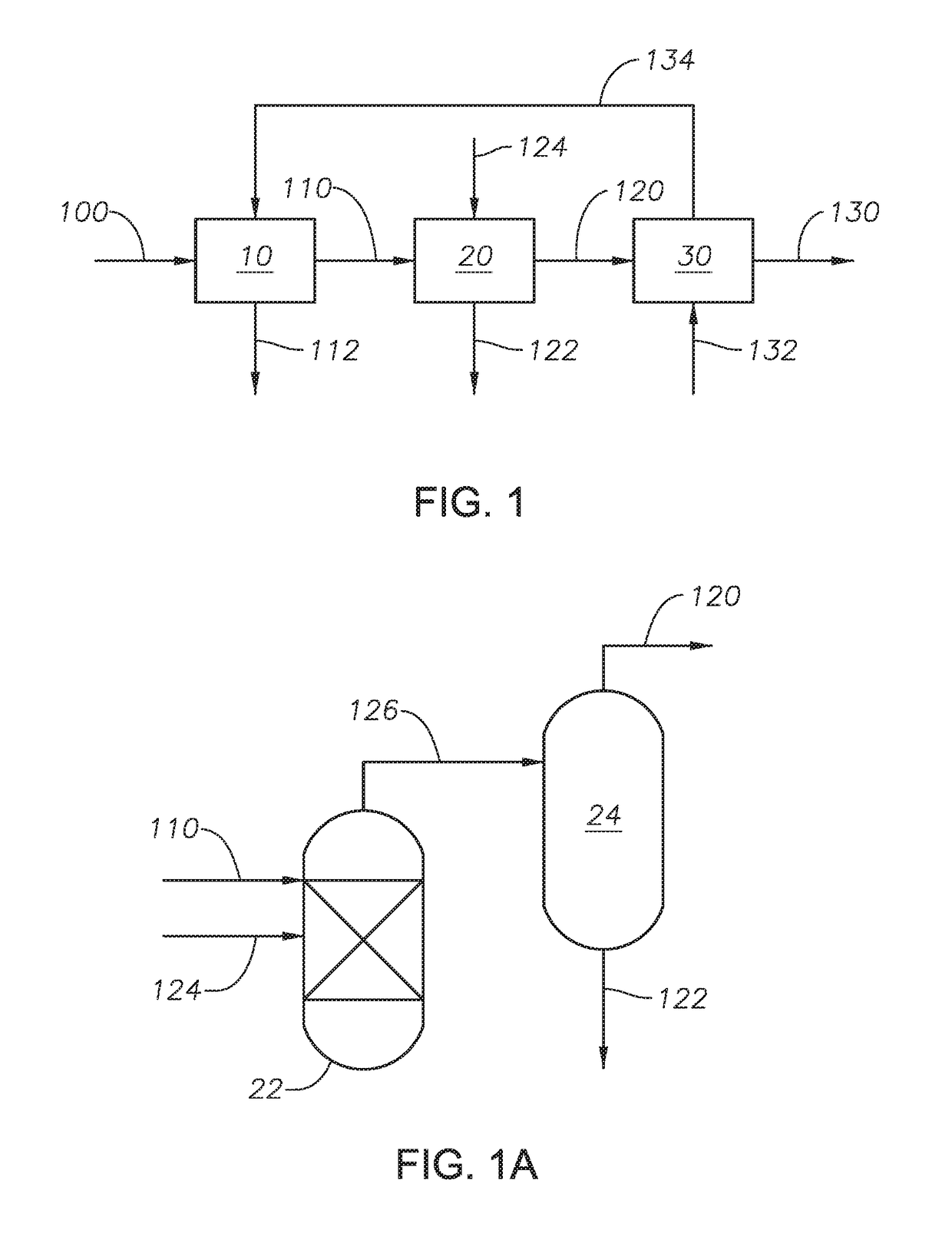
[0095]Example 1 was simulated based on the configuration embodied in FIG. 14, with reference to FIG. 2 as described and is a comparative example. The sulfur recovery unit is operated in split mode due to the low hydrogen sulfide content in acid gas feed 100. The simulation contained no membranes and no reducing unit. The simulation was based on catalytic unit 16 having three Claus catalytic stages in series. The reaction furnace outlet Claus process with three Claus catalytic stages in series. The reaction furnace temperature outlet was 2097° F. (1147° C.). The resulting concentrations of components for selected streams are shown in Table 2.

[0096]

TABLE 3Heat and Mass Balance of Streams for Example 1.Stream100300212224226110112C10.00280.00000.00000.00000.00000.00110.0000C20.00140.00000.00000.00000.00000.00060.0000CO20.69150.00000.28680.00040.00040.47210.0000H2S0.22760.00000.00260.00030.00010.00570.0000N20.00000.79210.48620.00000.00000.31630.0000H2O0.07620.00990.13420.02290.07050.1972...

example 2

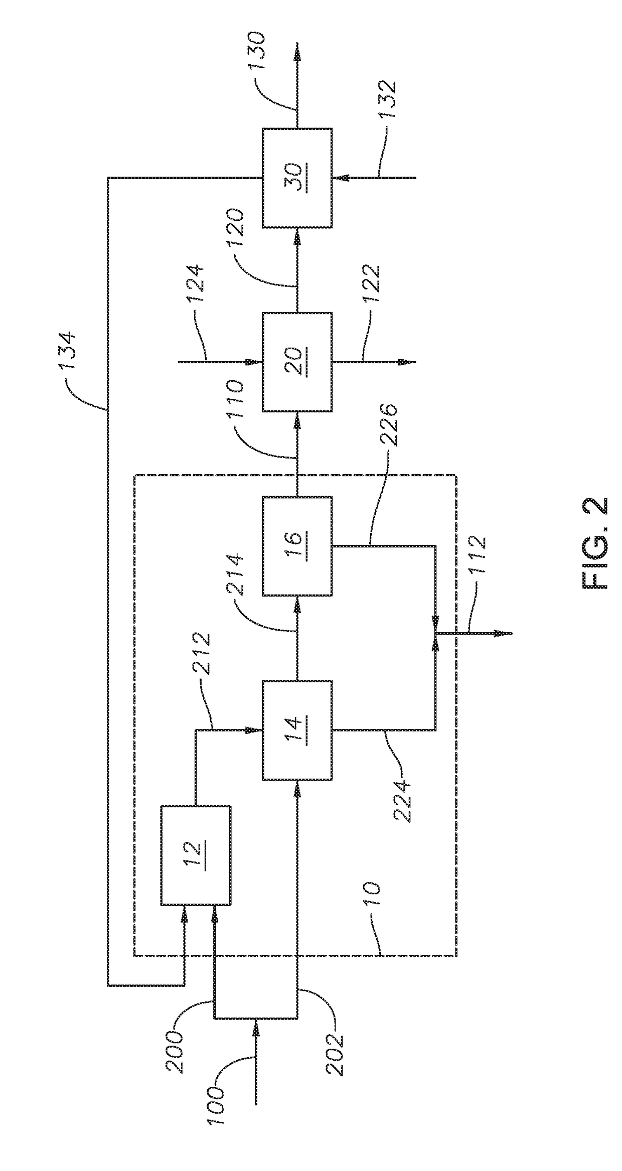
[0098]Example 2 was simulated based on the configuration embodied in FIG. 2 and described above. Sulfur recovery unit 10 is operated in split mode due to the low H2S content in acid gas feed 100. The simulation was based on catalytic unit 16 having three Claus catalytic stages. The reaction furnace temperature outlet was 1838.9° F. (1004° C.). The permeate of hydrogen sulfide membrane 30 was swept with air in sweep air feed 132. The membrane in hydrogen sulfide membrane 30 was a hydrogen sulfide-selective membrane area with the permeability specified in Table 2 and with a total area of 61,642 square meters (m2). The pressure of membrane feed 120 was 16 psig (280.6 kPa). The permeate pressure was set at −7 psig (53.1 kPa). The resulting concentrations of components for selected streams are shown in Table 4.

[0099]

TABLE 4Heat and Mass Balance of Streams for Example 2.Stream100132212224226120134112130C10.00280.00000.00000.00000.00000.00120.00010.00000.0013C20.00140.00000.00000.00000.000...

example 3

[0101]Example 3 was simulated based on the configuration embodied in FIG. 3. Sulfur recovery unit 10 is operated in split mode due to the low H2S content in acid gas feed 100. The simulation was based on catalytic unit 16 having three Claus catalytic stages. The reaction furnace temperature outlet was 1492.3° F. (811.4° C.). The membrane in hydrogen sulfide membrane 30 was a hydrogen sulfide-selective membrane area with the permeability specified in Table 2 and with a total area of 61,642 m2. The pressure of membrane feed 120 was 75 psig (618 kPa). The permeate pressure was set at 1 psig (108 kPa). The resulting concentrations of components for selected streams are shown in Table 5.

[0102]

TABLE 5Heat and Mass Balance of Streams for Example 3.Stream100300212224226120134112130C10.00280.00000.00000.00000.00000.00100.00030.00000.0012C20.00140.00000.00000.00000.00000.00050.00020.00000.0005CO20.69150.00000.45190.00040.00050.62600.35630.00000.5768H2S0.22760.00000.00170.00030.00010.00810.008...


PUM

PropertyMeasurementUnit
temperatureaaaaaaaaaa
pressureaaaaaaaaaa
pressureaaaaaaaaaa

Abstract

A method for removing sulfur-containing compounds from a sulfur recovery unit (SRU) tail gas stream includes the steps of introducing the SRU tail gas stream to a reducing unit to produce a membrane feed, the reducing unit configured to reduce the sulfur-containing compounds to hydrogen sulfide, introducing the membrane feed to a hydrogen sulfide membrane unit, the hydrogen sulfide membrane unit comprising a membrane, wherein the membrane feed comprises hydrogen sulfide, allowing the membrane feed to contact a feed side of the membrane such that hydrogen sulfide permeates through the membrane to a permeate side, and collecting the retentate gases that fail to permeate through the membrane to produce a stack feed, wherein the stack feed comprises retentate gases.

Description

TECHNICAL FIELD[0001]This invention relates to a system and method for improving sulfur recovery from a sulfur recovery unit. More specifically, this invention provides a system and method for treating acid gas streams and minimizing sulfur dioxide emissions therefrom.BACKGROUND OF THE ART[0002]As part of natural gas processing and hydro-treatment of oil fractions, a large amount of hydrogen sulfide (H2S) is produced. The H2S is toxic and therefore is converted to elemental sulfur (S), which is a more practical and safer state for handling and transportation. With more stringent fuel regulations and increasing environmental concerns, together with the need to process sourer crude oils and natural gases, sulfur recovery has become one of the leading issues in emission reduction. Elemental sulfur is the ultimate state of recovery of the sulfur species.[0003]The conversion of H2S into elemental sulfur is performed in a sulfur recovery unit (SRU). The level of sulfur recovery is increas...

Claims


Application Information

Patent Timeline
Patent Type & Authority Patents(United States)
IPC IPC(8): B01D53/22B01D53/40B01D53/26C01B17/16C01B17/04B01D53/75B01D53/74B01D53/62B01D53/52B01D53/48
CPCB01D53/226B01D53/229B01D53/265B01D53/52C01B17/0456C01B17/164B01D53/22B01D53/50B01D2251/202B01D2257/302B01D2257/304B01D2257/504Y02C20/40Y02P20/151
Inventor BALLAGUET, JEAN-PIERRE R.VAIDYA, MILIND M.HAMAD, FERASDUVAL, SEBASTIEN A.CHARRY-PRADA, IRAN D.
Owner SAUDI ARABIAN OIL CO
Why Eureka
Try Eureka