Asymmetric locking technique for asymmetric frequency locked loop

a technology of asymmetric locking and loop, which is applied in the direction of automatic control, electrical equipment, etc., can solve the problems of voltage loss, power supply voltage usually decreases, power consumption of integrated circuits,

Active Publication Date: 2018-04-24
ORACLE INT CORP
View PDF1 Cites 4 Cited by
  • Summary
  • Abstract
  • Description
  • Claims
  • Application Information

AI Technical Summary

Benefits of technology

[0013]In some embodiments, during normal operation of the clock-generation circuit, the Muller C-element selects the slowest of the outputs of the first and second DCOs. In this way, during a voltage undershoot of the power supply voltage, the gate-dominated delay characteristic determines the speed of the clock signal, and during a voltage overshoot of the power supply voltage, the wire-dominated delay characteristic determines the speed of the clock signal.

Problems solved by technology

However, in practice the power-supply voltage usually decreases when there is an increase in the power consumption of the integrated circuit.
In particular, when a transient increase in the power-supply current occurs, the inductance (L) through a chip package of the integrated circuit can result in a voltage loss
This voltage loss can possibly cause a failure on a critical path because of an insufficient timing margin caused by the voltage loss.
Note that if the power-supply voltage drops below Vlow, an error may arise in a critical path in the integrated circuit because of an insufficient timing margin.
This is because smaller critical dimensions are typically associated with higher clock frequencies, which increases power consumption and, thus, increases voltage droop.
(However, note that the voltage variations associated with this resonance frequency are typically at too high of a frequency to be addressed by a voltage regulator module in the power-supply distribution system, so it is not possible to deal with this resonance problem by simply changing the design of the voltage regulator module.)
Collectively, these effects may require additional voltage margin to be added when designing integrated circuits to ensure proper operation, and this additional voltage margin may increase cost, complexity and time to market for the integrated circuit.
However, when the outputs of the two DCOs, which are locked to the same target frequency, are combined at a C-element, the C-element introduces additional delay, which causes the clock-generation circuit to deviate from the target frequency.

Method used


Image

  • Asymmetric locking technique for asymmetric frequency locked loop
  • Asymmetric locking technique for asymmetric frequency locked loop
  • Asymmetric locking technique for asymmetric frequency locked loop

Examples


Embodiment Construction

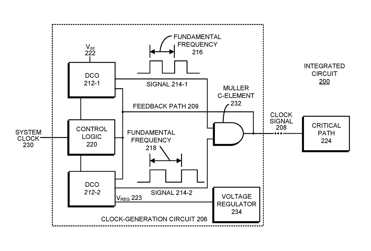
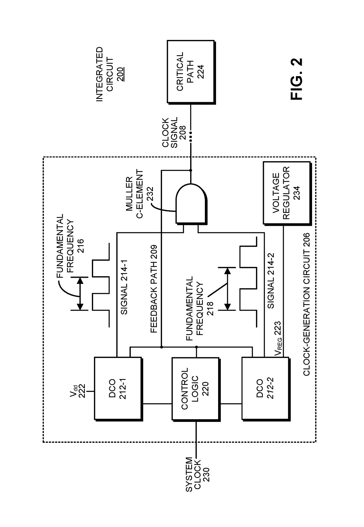
[0024]FIG. 2 presents a block diagram illustrating an integrated circuit 200 that includes a clock-generation circuit 206, which generates a clock signal 208 for a critical path 224 in integrated circuit 200. Clock-generation circuit 206 includes a digitally controlled oscillator (DCO) 212-1 that creates an output signal 214-1 having fundamental frequency 216, and a DCO 212-2 that creates an output signal 214-2 having fundamental frequency 218. Clock-generation circuit 206 also includes Muller C-element 232 that receives output signals 214-1 and 214-2 and selects the latest-arriving edges in received output signals 214-1 and 214-2 to produce a clock signal 208, which passes through a feedback path 209 into DCOs 212-1 and 212-2 and control logic 220. Control logic 220 also receives a system clock 230, which is used as a target frequency for calibrating DCOs 212-1 and 212-2.

[0025]In some embodiments, the power-supply voltage of DCO 212-2 is provided by a voltage regulator 234. In part...


PUM


Abstract

A system that generates a click signal includes a first digitally controlled oscillator (DCO) having a first fundamental frequency, and a second DCO having a second fundamental frequency. The system also includes a Muller C-element, which combines outputs of the first and second DCOs to produce the clock signal, which feeds back into the first and second DCOs. During a calibration operation, while the second DCO is set to a frequency larger than the target frequency, the system adjusts the first DCO with reference to a first feedback loop, which includes the first DCO, so that the clock signal matches the target frequency, and while the first DCO is set to the adjusted first fundamental frequency plus a frequency offset, the system adjusts the second DCO with reference to a second feedback loop, which includes the second DCO, so that the clock signal matches the target frequency.

Description

BACKGROUNDField[0001]The disclosed embodiments relate to clock-generation circuits that generate clock signals for integrated circuits, such as a processor chip. More specifically, the disclosed embodiments relate to a clock-generation circuit having an asymmetric frequency-locked loop (AFLL), which includes digitally controlled oscillators (DCOs), and which adjusts a clock frequency based on variations in a power-supply voltage.Related Art[0002]The operating frequency of an integrated circuit is typically specified at the lowest acceptable power-supply voltage (Vlow) for a critical path in the integrated circuit, i.e., the power-supply voltage for which the critical path has a non-zero timing margin. In addition, the power consumption of the integrated circuit is usually specified at the average power-supply voltage (Vnominal). In general, clock-generating circuits are designed to be stable and not to track variations in the power-supply voltage, such as changes associated with pow...

Claims


Application Information

Patent Timeline
Patent Type & Authority Patents(United States)
IPC IPC(8): H03L7/099H03L5/00H03L7/07H03L7/081
CPCH03L7/0991H03L7/0818H03L5/00H03L7/07H03L7/0995
Inventor YANGGONG, YIFANTURULLOLS, SEBASTIANHWANG, CHANGKUHUYNH, NICOLAS M.WOO, DANIEL S.
Owner ORACLE INT CORP
Why Eureka
Try Eureka