Short-circuit detection device and method used in inverter circuit

a short-circuit detection and inverter circuit technology, applied in power supply testing, emergency protective arrangements for limiting excess voltage/current, instruments, etc., can solve the problems of high probability of power device failure, inverter circuit is very likely to be damaged, damaged components or systems

Active Publication Date: 2018-05-01
DELTA ELECTRONICS (SHANGHAI) CO LTD
View PDF30 Cites 2 Cited by
  • Summary
  • Abstract
  • Description
  • Claims
  • Application Information

AI Technical Summary

Benefits of technology

[0008]The present disclosure provides a method for detecting a short circuit fault in a multi-level inverter circuit. The inverter circuit includes a plurality of single phase branches, each of which includes a plurality of switches. The short-circuit detection method includes transmitting at least a detection pulse sequence to the plurality of switches of the single phase branch; determining whether a conducting loop is formed in the single phase branch according to the detection pulse sequence; and determining a position of a malfunctioned switch of the single phase branch according to a path of the conducting loop when the conducting loop exists.

Problems solved by technology

However, the structure and the control mechanism of the circuit become more complicated as the level of the inverter circuit increases result in a higher probability of the failure of the power device.
Common conditions that cause failures, such as the existence of an open-circuited switch, a short-circuited switch, an incorrect wiring connection, a wiring disconnection or a unsuccessful driving condition, will damage the components or the system.
If there is no efficient way to determine that whether there is a short-circuited condition in the inverter circuit, the inverter circuit is very likely to be damaged during its operation and may do harm to, for instance, production delays or serious and catastrophic incidents.

Method used


Image

  • Short-circuit detection device and method used in inverter circuit
  • Short-circuit detection device and method used in inverter circuit
  • Short-circuit detection device and method used in inverter circuit

Examples


Embodiment Construction

[0020]Reference will now be made in detail to the present embodiments of the disclosure, examples of which are illustrated in the accompanying drawings. Wherever possible, the same reference numbers are used in the drawings and the description to refer to the same or like parts.

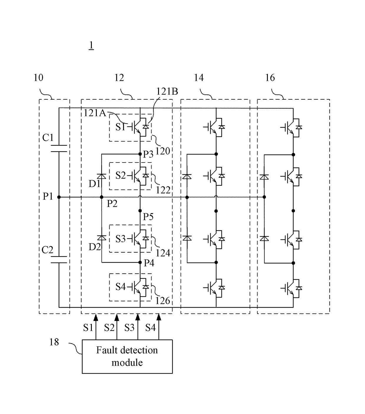
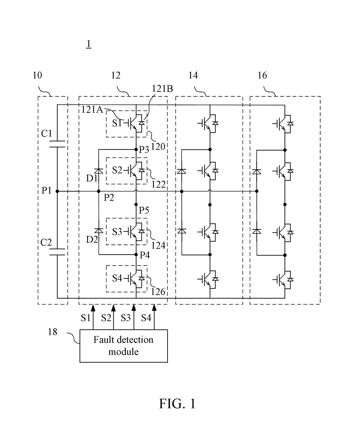
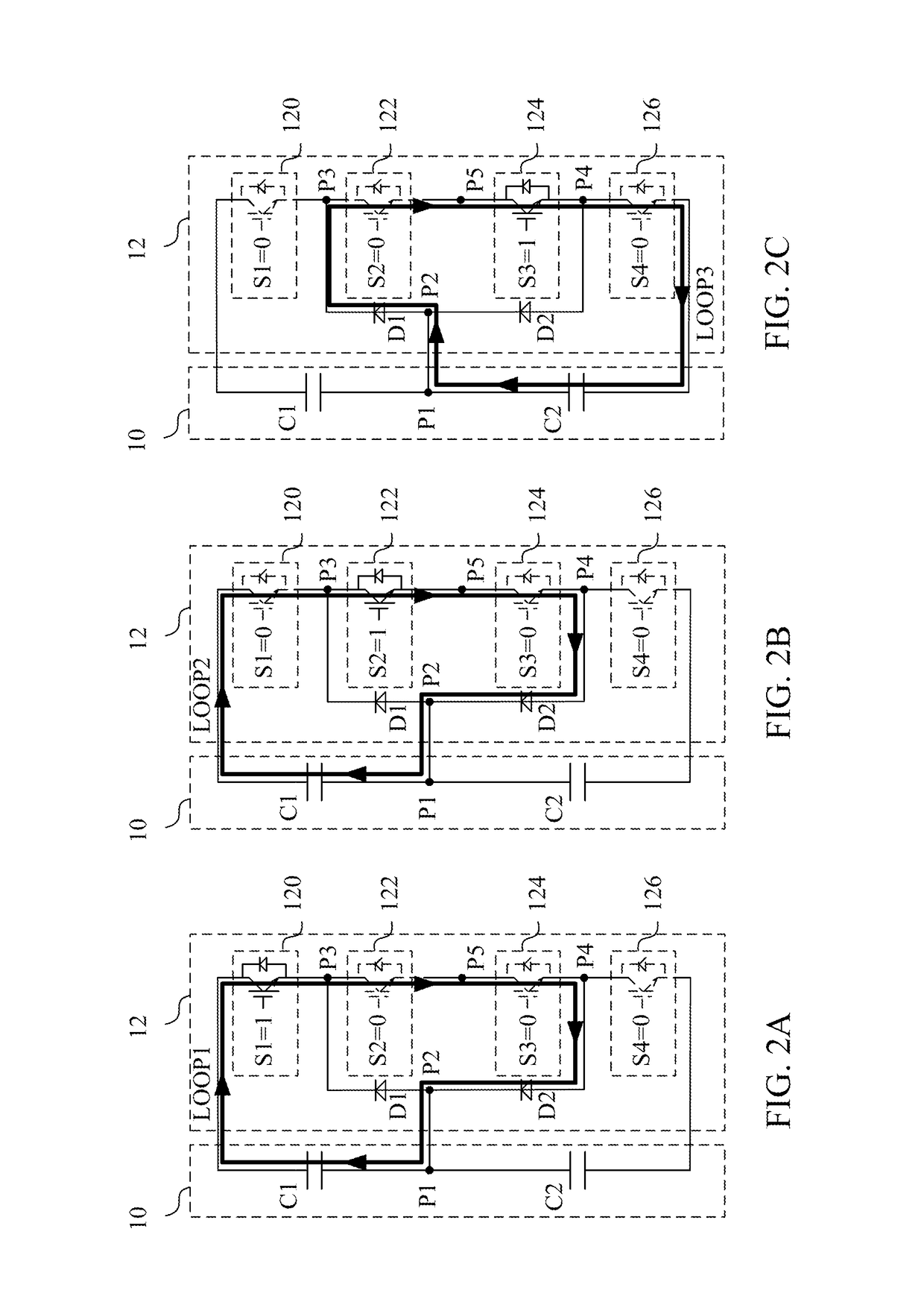
[0021]Reference is now made to FIG. 1. FIG. 1 is a circuit diagram illustrating an inverter circuit 1 according to an embodiment of the present disclosure. The inverter circuit 1 includes a capacitor module 10, single phase branches 12, 14 and 16, and a fault detection module 18.

[0022]The capacitor module 10 includes a first capacitor C1 and a second capacitor C2 electrically coupled in series via a first node P1. In an embodiment, the capacitor module 10 is coupled to other external circuits via a bus (not illustrated). The external circuit can be, for instance, a rectifier circuit (not illustrated), but is not limited thereto.

[0023]Each of the single phase branches 12, 14 and 16 is coupled to the capacitor ...


PUM


Abstract

A method for detecting a short circuit fault in a multi-level inverter circuit is provided. The multi-level inverter circuit includes a plurality of single phase branches each including of switches. The method includes steps outlined below. At least one detecting pulse sequence is transmitted to the switches of each of the single phase branches. Whether a conducting path is formed in any of the single phase branches is determined according to the detecting pulse sequence. When the conducting loop is formed, respective position of one or more malfunctioned switch in the single phase branches is located according to a path of the conducting loop. A short-circuit detection device and a three-phase three-level inverter circuit are also disclosed herein.

Description

RELATED APPLICATIONS[0001]This application claims priority to Chinese Application Serial Number 201410241037.3, filed May 30, 2014, which is herein incorporated by reference.BACKGROUND[0002]Field of Invention[0003]The present disclosure relates to an inverter technology. More particularly, the present disclosure relates to a short-circuit detection device and method used in an inverter circuit.[0004]Description of Related Art[0005]Inverters are commonly utilized in power systems and users have higher and higher expectations to the maintainability. Taking a multi-level inverter as an example, the multi-level inverter is especially useful in applications requiring high voltage and high power. However, the structure and the control mechanism of the circuit become more complicated as the level of the inverter circuit increases result in a higher probability of the failure of the power device. The system reliability is significantly decreased.[0006]Common conditions that cause failures, ...

Claims


Application Information

Patent Timeline
Patent Type & Authority Patents(United States)
IPC IPC(8): H02H7/122H02M1/32H02H9/02G01R31/02H02M7/487G01R31/25G01R31/42H02H1/00
CPCH02H7/1225G01R31/025G01R31/42H02M1/32H02M7/487H02H9/02H02H1/0007G01R31/52
Inventor LIU, LIANGPU, BO-YUZHANG, YIGAN, HONG-JIANYING, JIAN-PING
Owner DELTA ELECTRONICS (SHANGHAI) CO LTD
Why Eureka
Try Eureka