Method and apparatus for accelerated magnetic resonance imaging

a magnetic resonance imaging and acceleration factor technology, applied in the field of magnetic resonance imaging, can solve the problems of limited choice of larger acceleration factor of pat technique, various limitations and disadvantages of techniques, and low signal-to-noise ratio

Active Publication Date: 2018-05-15
SIEMENS HEALTHCARE GMBH
View PDF10 Cites 2 Cited by
  • Summary
  • Abstract
  • Description
  • Claims
  • Application Information

AI Technical Summary

Benefits of technology

[0019]The measurement duration can be reduced as a result of the undersampling acquisition of the MR data in accordance with the different undersampling schemes. At the same time, a comparatively large signal-to-noise ratio can be achieved for the different MR contrasts or the result image as a result of using the different undersampling schemes. A noise component caused by the reconstruction by means of PAT techniques can be comparatively small. Accordingly, the magnetic parameter can then be determined with greater precision.
[0022]Generally, the undersampling schemes can be chosen such that a deviation between the different undersampling schemes has no, or only a minor, systematic characteristic. It would, however, also be possible to choose the undersampling schemes as systematically different. In such a way a systematic sampling of the k-space—considered across all undersampling schemes—can be achieved; this can in turn reduce the noise component caused by the PAT techniques.
[0028]Therefore, MR data may be acquired for a first k-space point in accordance with a first undersampling scheme and MR data may be acquired for a second k-space point in accordance with a second undersampling scheme, wherein the first and second undersampling schemes are assigned to MR contrasts adjacent in time and the first and second k-space points are arranged adjacent to one another along the k-space trajectory in the k-space. In this way a systematic variation of the undersampling schemes can be achieved from MR contrast to MR contrast; this enables a particularly high quality of the MR contrasts or, as the case may be, a particularly precise determination of the result image.
[0033]In such an implementation it may then be possible to adapt the signal model in each case for each pixel of the result image in a second step to the corresponding MR data or, as the case may be, to the reconstructed data of the MR contrasts. The reconstruction or antialiasing can therefore be carried out initially by means of PAT techniques and then the signal model can be adapted to the data obtained in that way. This can enable a particularly simple or rapid implementation of the determining of the result image.
[0035]In other words it may be possible, in a single numeric optimization—which determines e.g. an extreme value of a magnitude for a parameter space as solution—to carry out both the reconstruction by means of PAT techniques and the adaptation of the signal model within the framework of chemical-shift MR imaging or parametric MR imaging. It may then be unnecessary to reconstruct missing information initially in a separate first step and reduce aliasing artifacts. This can enable the determining of the result image to be carried out in a particularly precise and rapid manner.
[0041]As a result of the combined reconstruction and adaptation of the signal model, a particularly simple, rapid and precise determination of the result image can be made possible.

Problems solved by technology

However, such techniques have various limitations and disadvantages.
The choice of larger acceleration factors of the PAT technique is often limited by the performance capability of the coil configuration of the respective MR system: a so-called g-factor can increase if a larger acceleration factor is chosen, cf.
For this reason it is possible—e.g. given a certain reduction in the measurement duration—to obtain only a comparatively poor signal-to-noise ratio of the MR contrasts; as a result an accuracy with which the MR parameter can be determined may be limited.

Method used


Image

  • Method and apparatus for accelerated magnetic resonance imaging
  • Method and apparatus for accelerated magnetic resonance imaging
  • Method and apparatus for accelerated magnetic resonance imaging

Examples


Embodiment Construction

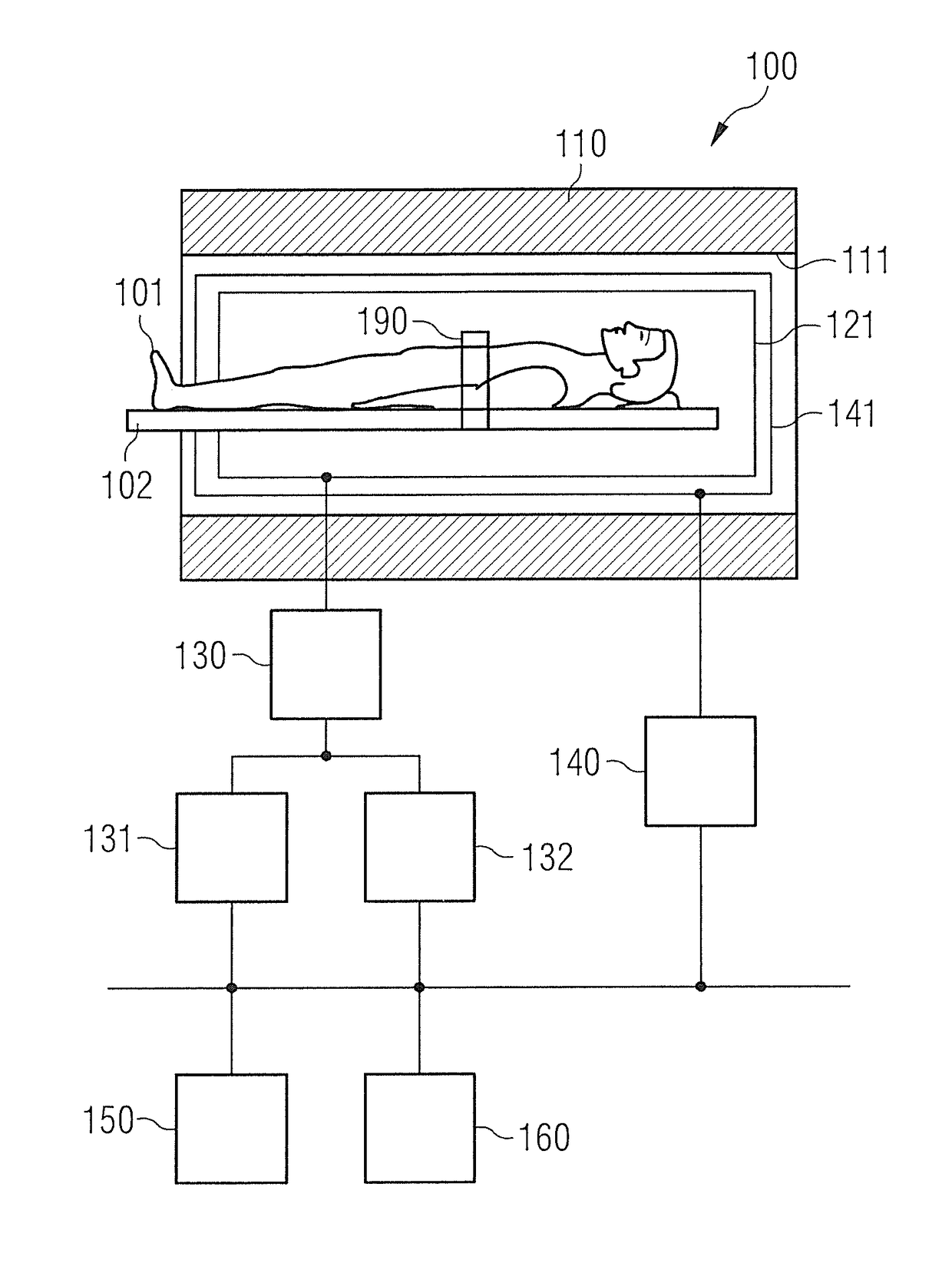
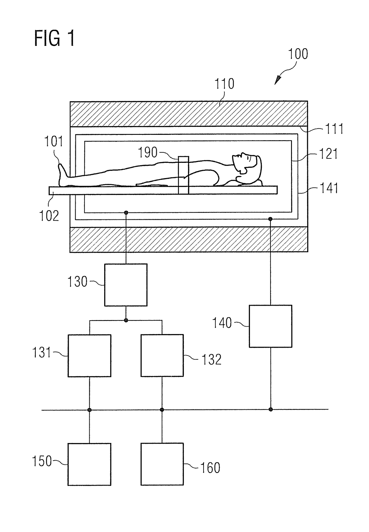
[0059]The invention is explained in more detail below with reference to the drawings. In the figures, like reference signs designate identical or similar elements. The figures are schematic representations of different embodiment variants of the invention. Elements shown in the figures are not necessarily drawn to scale. Rather, the different elements represented in the figures are depicted in such a way that their function and general purpose are rendered intelligible to the person skilled in the art. Connections and couplings represented in the figures between functional units and elements may also be implemented as an indirect connection or coupling. A connection or coupling may be implemented as wired or wireless. Functional units may be implemented in the form of hardware, software or a combination of hardware and software.

[0060]PAT techniques are explained in the following in connection with chemical-shift MR imaging or parametric MR imaging. The shifting of the undersampling ...


PUM


Abstract

In a method and apparatus for magnetic resonance (MR) imaging, a result image is provided based on multiple MR contrasts. The result image is indicative of a value of a magnetic parameter. MR data are acquired for the multiple contrasts at different time points, in each case following preparation of a magnetization. During the acquisition of the MR data, k-space is undersampled according to a respective undersampling scheme. The undersampling schemes of the different MR contrasts are different from one another.

Description

BACKGROUND OF THE INVENTION[0001]Field of the Invention[0002]The invention relates to methods for magnetic resonance imaging and to corresponding magnetic resonance systems. The invention relates in particular to magnetic resonance imaging techniques in which different undersampling schemes are used for different magnetic resonance contrasts.[0003]Description of the Prior Art[0004]Magnetic resonance (MR) imaging techniques are known in which a result image is obtained which is indicative of a magnetic parameter in an examination region of interest. For example, the magnetic parameter can correspond to a fraction of a fat spin species or a water spin species in the examination region; in such a case reference is often made to Dixon-type techniques, which allow a water-fat separation. Generally, such techniques which permit the separation of different spin species are also referred to as chemical-shift imaging. It is also possible for the magnetic parameter to correspond e.g. to a T1 ...

Claims


Application Information

Patent Timeline
Patent Type & Authority Patents(United States)
IPC IPC(8): G01V3/00G01R33/56G01R33/561A61B5/055G01R33/48G01R33/485G01R33/50
CPCG01R33/561A61B5/055G01R33/5602G01R33/485G01R33/5616G01R33/4828G01R33/50G01R33/5611G01R33/4818
Inventor FEIWEIER, THORSTENNICKEL, MARCEL DOMINIK
Owner SIEMENS HEALTHCARE GMBH
Why Eureka
Try Eureka