Valve which depressurises, and a valve system

a valve system and valve valve technology, applied in the field of mechanical valves, can solve the problems of insufficient approach, large logistical problems in sample preparation and analysis, and sample loss in transit, and achieve the effect of minimising the risk of fluid sample leakage in the use of sampl

Active Publication Date: 2018-06-12
ATLAS GENETICS
View PDF116 Cites 0 Cited by
  • Summary
  • Abstract
  • Description
  • Claims
  • Application Information

AI Technical Summary

Benefits of technology

[0015]In a first aspect of the invention, there is provided a valve system in a fluidic cartridge for depressurising a fluid sample processing region, comprising: a network of channels forming the fluid sample processing region, the network of channels fluidly connected to a first channel for introducing a fluid sample into the network of channels, the first channel having an isolation valve therein, the isolation valve actuatable to seal off the network of channels and thereby create a closed system therein. Thus, the isolation valve is provided between the first channel and the network of channels. The valve system further comprises a control valve interrupting a second channel within the network of channels, the control valve having a valve chamber coupled to the second channel via first and second openings, the valve chamber configured such that it has a first volume when the valve is closed to prevent fluid from flowing between the first and second openings, and a second, larger, volume when the valve is open to permit fluid to flow between the first and second openings; wherein the valve system is operable to depressurise the fluid sample processing region by closing the control valve to decrease the total volume within the network of channels, actuating the isolation valve to seal off the network of channels and thereby create a closed system within the network of channels, and opening the control valve to increase the total volume within the closed system of the network of channels. Because the isolation valve is the only point at which fluid may be introduced into the network of channels, when the isolation valve is closed, the network of channels is a completely sealed system with no further entry or exit points. By depressurising the fluid sample processing region after use, the risk of leakage of fluid sample is minimised in used cartridges.

Problems solved by technology

Sample preparation and analysis presents many logistical problems.
This approach is inadequate.
Firstly, there is a significant risk that a sample is lost in transit or mismatched with the wrong patient.
Moreover, whilst recent developments in technology have reduced the overall time taken to conduct the test, the delay involved in sending the sample to a laboratory is unsatisfactory.
Nevertheless, analytical systems of the kind found in laboratories are complex and it is often difficult to provide sufficient amounts of pure targets from source samples to reliably perform downstream analytical assays.
This typically prohibits local GP surgeries from being able to carry out such tests on site.
However, it has been found that handling a sample in a microfluidics device can be very difficult.
In such small channels as are found on a conventional LOC, it is difficult to apply external forces to move the sample from one site to another to perform different actions on the sample.
There is also a limit to the complexity of a LOC device which operates purely using capillary action.
Furthermore, owing to the small sample sizes of LOC's, the devices have reduced sensitivity and the probability of a target being present in the sample is thus reduced.
This is because any leakage of sample could not only lead to contamination, but may lead to false positives in future test runs.
The need to minimise leakage from a microfluidics system is particularly acute in devices which employ PCR technology since the target DNA is amplified and increases the risk of causing false positive results.

Method used


Image

  • Valve which depressurises, and a valve system
  • Valve which depressurises, and a valve system
  • Valve which depressurises, and a valve system

Examples


Embodiment Construction

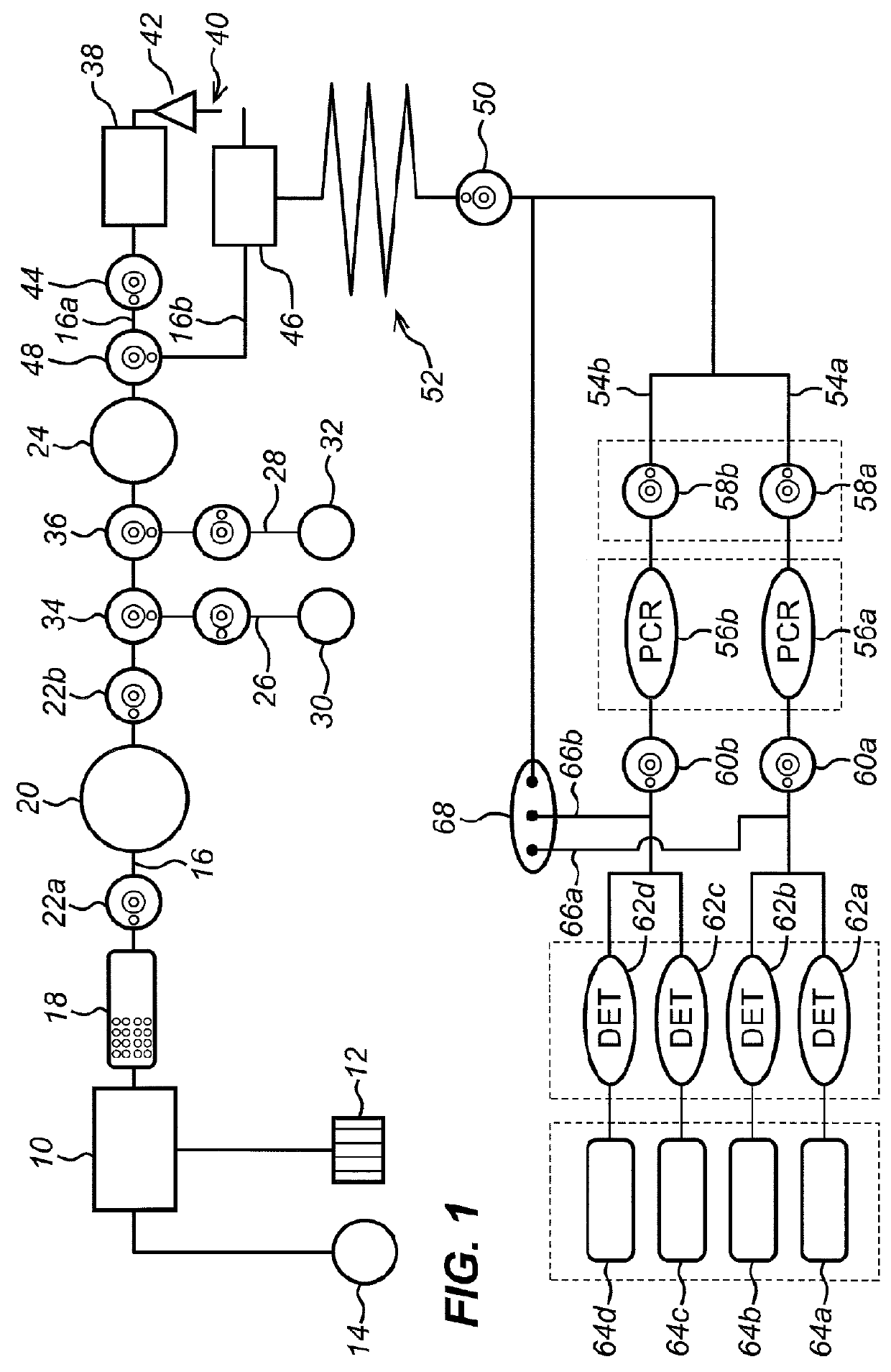
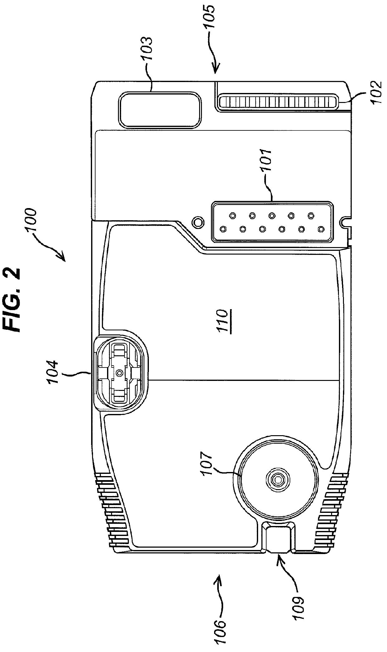
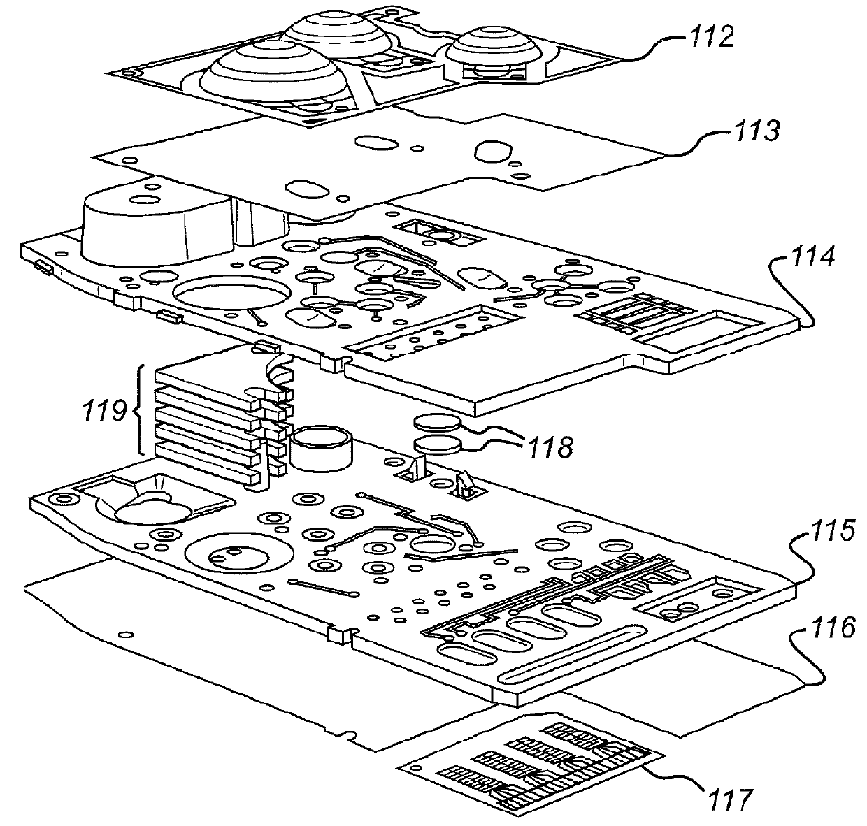
[0070]Embodiments of the invention will now be described in the context of an exemplary fluid cartridge in which the invention is implemented. Whilst not necessary to understand the present invention, it is beneficial to provide general description of the principles of the structure, manufacture, function and use of the fluidic cartridge and associated methods for performing a test.

[0071]The exemplary fluidic cartridge and associated methods chosen to illustrate the present invention are for the detection of Chlamydia trachomatis bacterium using PCR amplification and electrochemical detection. However, the skilled person would understand that the invention is not limited to the exemplary fluidic cartridge and associated methods, and is suitable for use in with various different cartridges for a wide variety of sample analysis techniques or biological assays; for example, assays of target nucleic acid sequences in a liquid sample.

[0072]Those skilled in the art will understand that th...


PUM


Abstract

A valve for a fluidic cartridge is provided. The valve comprises a valve cavity having first and second openings connected to first and second passageways, respectively; and a flexible membrane within the valve cavity, the flexible membrane having a first portion actuatable to seal against the first opening and a second portion actuatable to seal against the second opening; wherein the valve cavity is configured such that the first flexible membrane portion may be actuated independently of the second flexible membrane portion to enable the first opening to be sealed independently of the second.

Description

CROSS-REFERENCES TO RELATED APPLICATIONS[0001]This application is a national stage application, filed under 35 U.S.C. § 371, of International Application No. PCT / GB2014 / 052304, filed on Jul. 28, 2014, and claims the benefit of, and priority to GB Patent Application No. 1313527.2, filed Jul. 29, 2013, the contents of each of which are incorporated hereby by reference in its entirety and for all purposes.FIELD[0002]The present invention relates to a valve for a fluidic cartridge and more particularly to a mechanical valve which may be used to depressurise a valve system.BACKGROUND[0003]Sample preparation and analysis presents many logistical problems. Conventionally, many medical samples (such as blood, saliva, urine and swab eluate) are provided to a doctor, for example a general practitioner doctor (GP) or a principle care physician (PCP), in a local surgery without the equipment necessary to analyse the sample. Hence, the sample must be sent to a laboratory where the sample is anal...

Claims


Application Information

Patent Timeline
Patent Type & Authority Patents(United States)
IPC IPC(8): B01L3/00F16K99/00
CPCB01L3/502738F16K99/0015B01L2200/0605F16K2099/0084B01L2400/0481B01L2400/0487B01L2400/0638B01L2200/0689B01L3/00B01L3/50B01L3/502B01L3/5027
Inventor TAYLOR, JAY KENDALLARLETT, BEN
Owner ATLAS GENETICS
Why Eureka
Try Eureka