Contamination control of gaseous emissions by corona-discharge generation of plasma

a technology of corona discharge and plasma, which is applied in the direction of lighting and heating apparatus, combustion types, separation processes, etc., can solve the problems of relatively expensive plasma generation by corona discharge process, and achieve the effect of reducing and less costly power consumption, reducing the required electrical energy consumption, and effected more efficiently

Inactive Publication Date: 2004-05-04
THE UNITED STATES OF AMERICA AS REPRESENTED BY THE SECRETARY OF THE NAVY
View PDF5 Cites 9 Cited by
  • Summary
  • Abstract
  • Description
  • Claims
  • Application Information

AI Technical Summary

Benefits of technology

Pursuant to the present invention, a corona discharge system is utilized to generate plasma for elimination of contaminants such as air polluting oxides within emission gas discharged from hot chamber incinerators. Use of the corona discharge system is rendered economically suitable because of reduced and less costly power consumption associated with the generation of plasma to which the contaminants are exposed. Such corona discharge system involves the supply of electrical pulse energy, ...

Problems solved by technology

It is also generally known that such plasma may be generated by a corona discharge process that is relatively costly...

Method used


Image

  • Contamination control of gaseous emissions by corona-discharge generation of plasma
  • Contamination control of gaseous emissions by corona-discharge generation of plasma
  • Contamination control of gaseous emissions by corona-discharge generation of plasma

Examples


Embodiment Construction

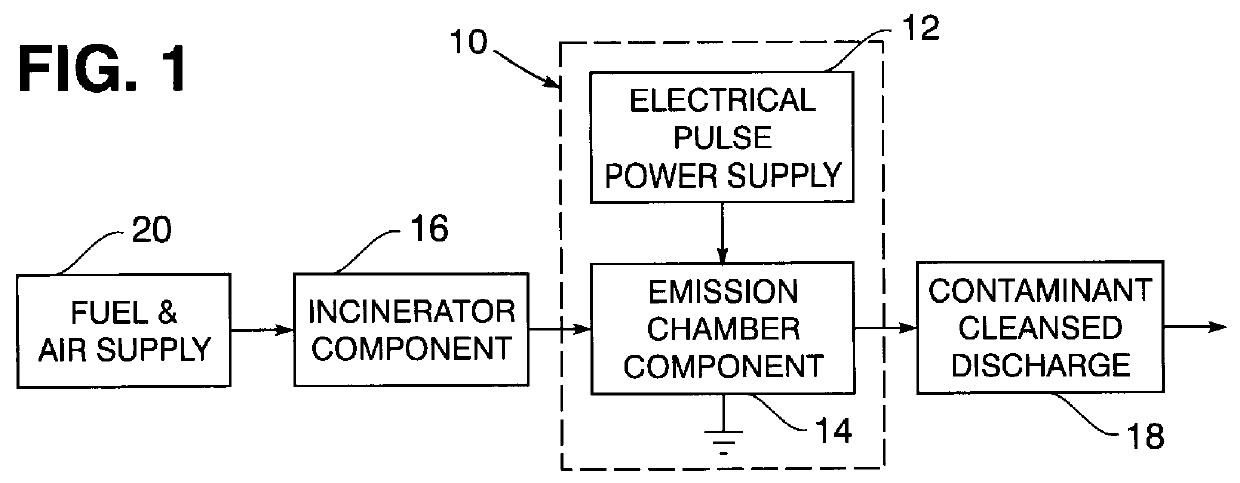
Referring now to the drawing in detail, FIG. 1 diagrams a corona discharge control system generally referred to by reference numeral 10, having an electrical pulse power supply 12 operationally connected to an emission chamber component 14. Pursuant to the present invention, the gas emission from an incinerator component 16 embodied in or associated with equipment or devices is decontaminated during passage through the emission chamber component 14 of the system 10 to provide a contaminant cleansed discharge 18 as diagrammed in FIG. 1. Such discharge 18 is in the form of a clean air emission where fuel and air from a supply 20 undergoes burning in the incinerator component 16.

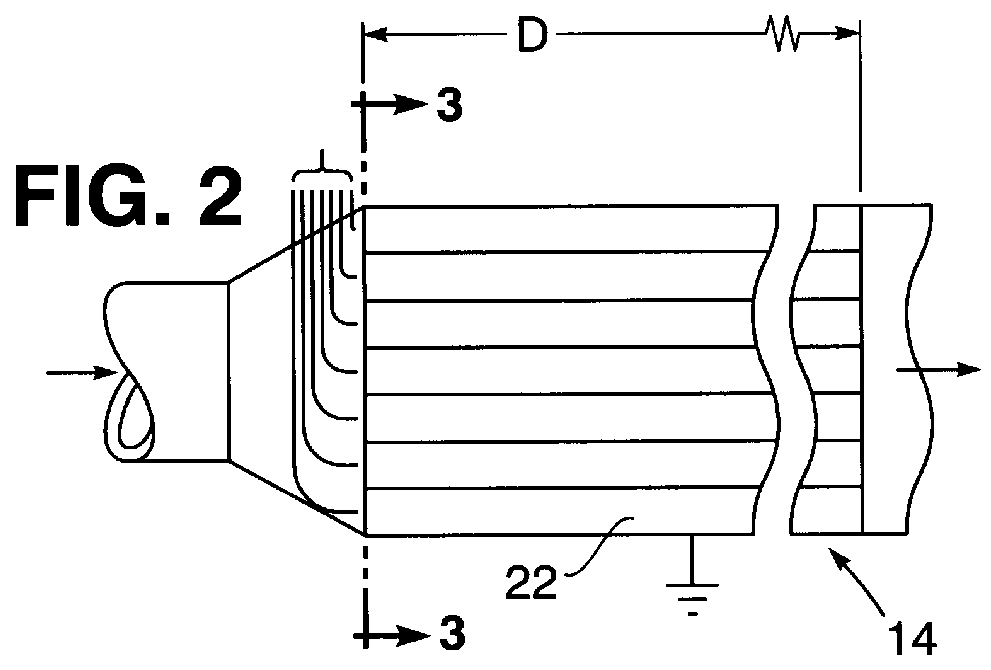
A gas emission from the incinerator component 16 maintained at a relatively high temperature (T) passes through the emission chamber component 14 having a flow passage length (D) as denoted in FIG. 2. As shown in FIG. 3, the flow passage through chamber component 14 is enclosed within an electrically grounded h...


PUM


Abstract

Contaminants within the gaseous emission discharged from an incinerator are eliminated during passage in parallel through reactor chambers by chemical reaction induced during exposure to plasma generated within said chambers. The plasma is generated by corona-discharge breakdown of electric fields established about electrodes within the reactor chambers upon supply thereto of electrical pulse voltage exceeding a critical field breakdown value inversely proportional to a high chamber temperature of the gaseous emission under atmospheric pressure within the reactor chambers.

Description

BACKGROUND OF THE INVENTIONThe elimination of contaminants from gaseous emissions by exposure to plasma under controlled conditions, is generally known in the art as disclosed for example in U.S. Pat. No. 5,137,701 to Mundt and in applicant's prior U.S. Pat. No. 5,468,356. The plasma according to such prior art disclosures is generated by use of microwave radiation. It is also generally known that such plasma may be generated by a corona discharge process that is relatively costly, involving impact ionization of neutrals by electrons accelerated by a high level electric field within a gaseous medium. It is therefore an important object of the present invention to provide a less costly method of eliminating contaminants from gaseous emissions by exposure to a plasma during its generation by a corona discharge process.SUMMARY OF THE INVENTIONPursuant to the present invention, a corona discharge system is utilized to generate plasma for elimination of contaminants such as air polluting...

Claims


Application Information

Patent Timeline
IPC IPC(8): A62D3/00B01D53/34B01J19/12B01D53/32F23G7/06A62D3/178A62D3/19A62D101/20A62D101/22A62D101/28A62D101/40
CPCF23G7/061B01D53/32B01D53/34B01J19/126F23G2204/201F23G2204/203
Inventor UHM, HAN S.
Owner THE UNITED STATES OF AMERICA AS REPRESENTED BY THE SECRETARY OF THE NAVY
Why Eureka
Try Eureka