Combined cycle with steam cooled gas turbine

Inactive Publication Date: 2000-01-18
GENERAL ELECTRIC CO
View PDF16 Cites 25 Cited by
  • Summary
  • Abstract
  • Description
  • Claims
  • Application Information

AI Technical Summary

Benefits of technology

3. Control of the HP steam temperature is accomplished by the steam attemperation system which bypasses a section of the HP superheater. This system eliminates the potential for contaminants to enter the steam as can occur with attemperation with feed water. Attemperation steam is extracted after it passes through one pass in the superheater to assure that it

Problems solved by technology

(1) Air Cooled Gas Turbine--The gas turbine high temperature components are cooled by air extracted or conducted from other components in the cycle. The steam cycle and the gas turbine coolant streams are not integrated.
(2) Water Cooled Gas Turbine--The gas turbine high temperature components are cooled with water in the liquid phase. The heat extracted from the high temperature gas turbine components is integrated with the combined cycle steam bottoming cycle. The energy extracted from the high temperature section of the gas turbine is transported to the low temperature portion of the steam cycle to maintain the water in the liquid phase, thus compromising thermal efficiency of the c

Method used


Image

  • Combined cycle with steam cooled gas turbine
  • Combined cycle with steam cooled gas turbine
  • Combined cycle with steam cooled gas turbine

Examples


Embodiment Construction

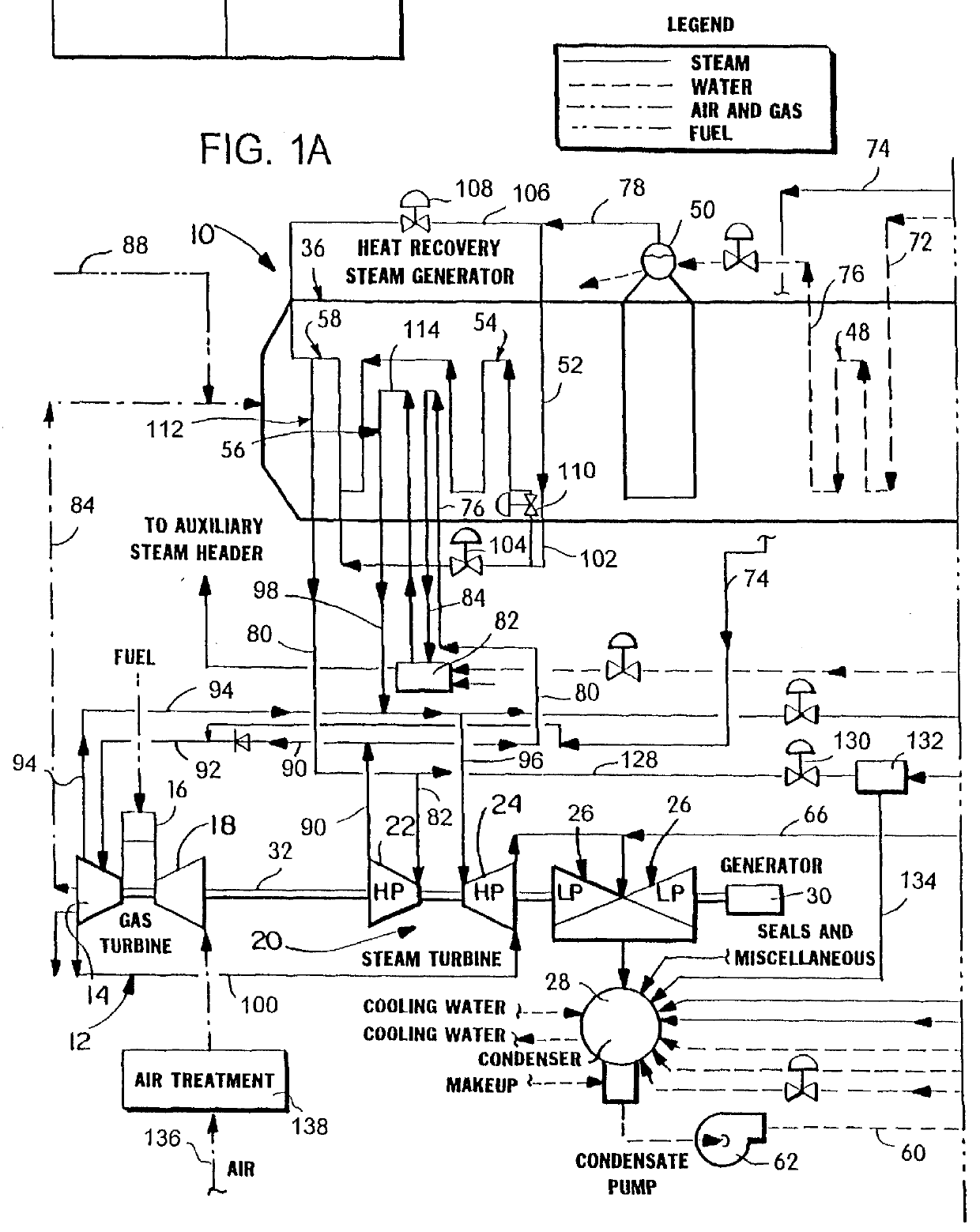
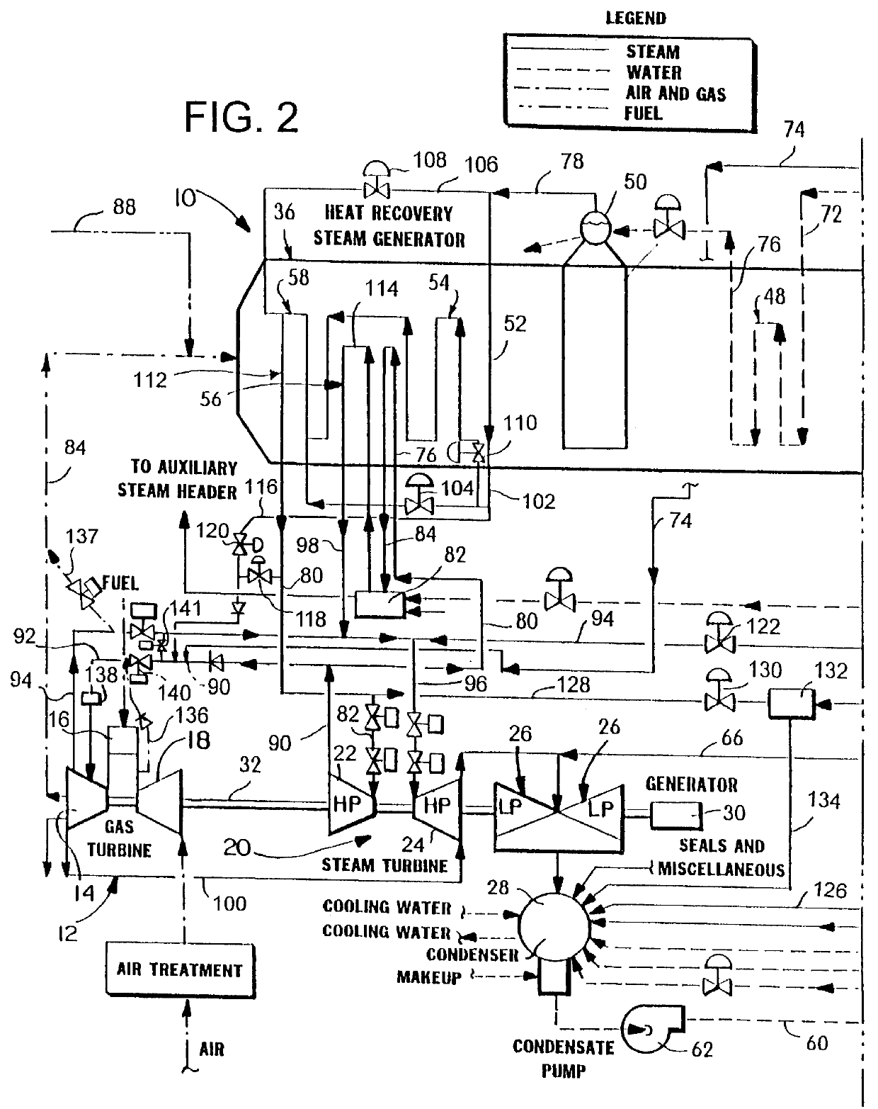
With reference to FIGS. 1A and 1B, the invention is incorporated in a multi-pressure reheat combined cycle power generation system 10. In the preferred embodiment, there is included a gas turbine system 12 comprising a compressor 18, a combustion system 16 and a gas turbine 14. A steam turbine system 20 includes a high pressure section 22, an intermediate pressure section 24 and one or more low pressure sections 26 with multiple steam admission points at different pressures. The low pressure section 26 exhausts to a condenser 28. The steam turbine drives the generator 30 which produces electrical power. The gas turbine 12, steam turbine 20 and generator 30 are arranged in tandem on a single shaft 32.

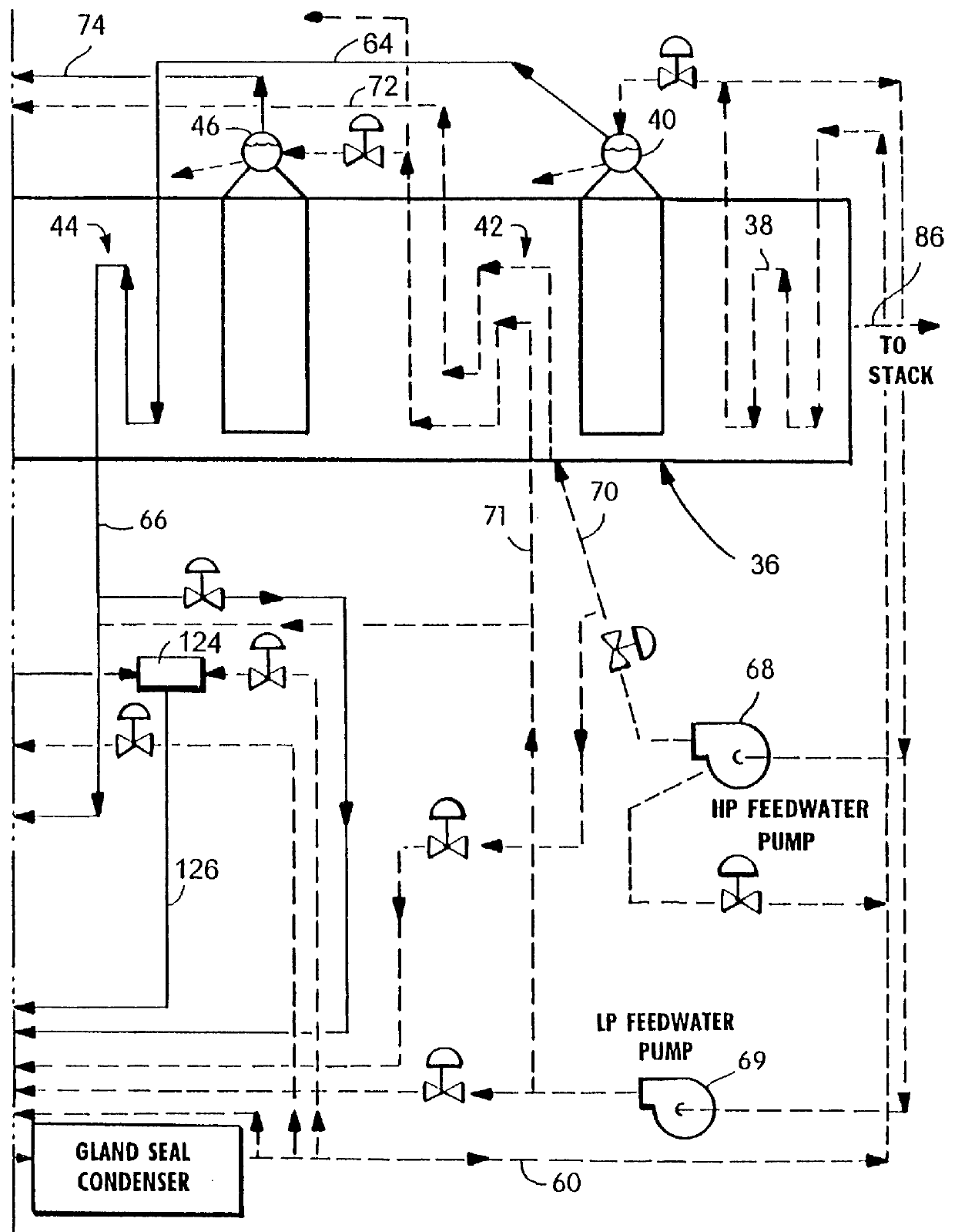
The combined cycle system as described herein includes a multi-pressure HRSG 36 which includes a low pressure (LP) economizer 38, an LP evaporator 40, an HP and IP economizer 42, a low pressure superheater 44, an IP evaporator 46, an HP economizer 48, an HP evaporator 50, a first HP supe...


PUM


Abstract

In a method of operating a combined cycle system including a gas turbine, a steam turbine and a multi-pressure heat recovery steam generator, an improvement includes supplying gas turbine cooling duty steam from a high pressure section of the steam turbine and from an intermediate pressure evaporator in the multi-pressure heat recovery steam generator, conducting the gas turbine cooling duty steam to the gas turbine for cooling hot gas turbine parts, and then returning the gas turbine cooling duty steam to an intermediate pressure section of the steam turbine. In a start-up procedure, steam is extracted from a first pass of a high pressure superheater in the multi-pressure heat recovery steam generator, mixed with steam discharged from the high pressure superheater and then supplied to the gas turbine cooling duty system. In this same start-up procedure, the gas turbine cooling duty steam is returned to the system condenser, bypassing the intermediate pressure section of the steam turbine. Related apparatus is also disclosed.

Description

TECHNICAL FIELDThis invention relates to a combined cycle power generation system in which exhaust gases from a gas turbine are recovered in an unfired, multi-pressure, heat recovery steam generator, and in which steam from the steam turbine exhaust and from the heat recovery steam generator intermediate pressure evaporator is utilized to cool the gas turbine stage 1 and 2 nozzles and buckets.BACKGROUND PRIOR ARTIn typical combined cycle power generation systems, cooling of gas turbine high temperature components and the accompanying steam cycle are usually of the following types:(1) Air Cooled Gas Turbine--The gas turbine high temperature components are cooled by air extracted or conducted from other components in the cycle. The steam cycle and the gas turbine coolant streams are not integrated.(2) Water Cooled Gas Turbine--The gas turbine high temperature components are cooled with water in the liquid phase. The heat extracted from the high temperature gas turbine components is in...

Claims


Application Information

Patent Timeline
IPC IPC(8): F01K23/10F02C7/16F02C6/18F02C7/18
CPCF01K23/106F02C6/18F02C7/16F02C7/18Y02E20/16F05D2260/2322
Inventor TOMLINSON, LEROY O.
Owner GENERAL ELECTRIC CO
Why Eureka
Try Eureka