

Field emission cathode
- Summary
- Abstract
- Description
- Claims
- Application Information
AI Technical Summary
Benefits of technology
Problems solved by technology
Method used
Image

Examples
Embodiment Construction
Below it will be explained, by way of an example, how field emission cathodes of carbon nano-cylinders can be produced, such as can be used, for example, as cathodes for diodes or switches. By way of a second example, it will be explained how field emission cathodes for a field emitter array can be produced by the methods of microstructure technology. Example: Production of individual cathodes on a knife edge
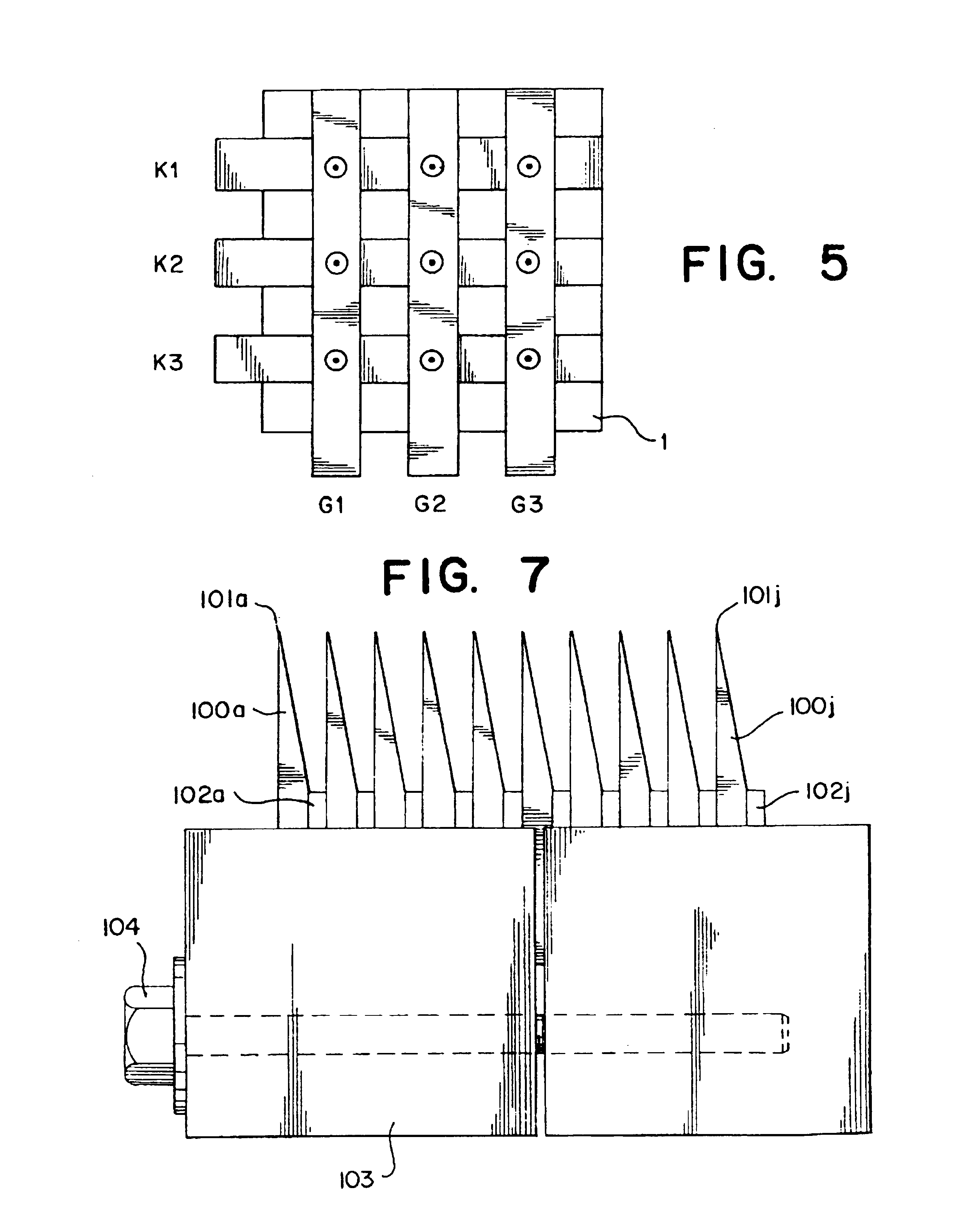
Square graphite wafers about 1 cm (centimeter) on a side, and 1 mm (millimeter) thick are ground or etched to a knife edge on one side. FIG. 6 shows such a graphite wafer 100 with a knife edge 101, beveled on one side. FIG. 7 shows how ten of these graphite wafers 100a to 100j are collected together into a block in a clamping fixture 103, in such a way that the knife edges 101a to 101j on one side of the block lie in one plane and an aluminum foil or Teflon foil is situated between each of the graphite wafers as a spacer 102a to 102j. The clamping fixture consists of two brass b...
PUM
 Abstract
Description
Claims
Application Information