Method and devices for laser induced fluorescence attenuation spectroscopy

a laser and fluorescence attenuation technology, applied in the direction of luminescent dosimeters, optical radiation measurement, diagnostics using spectroscopy, etc., can solve the problems of difficult to perform attenuation measurements on certain types of samples, and limited material application of techniques, etc., to achieve the effect of maximum signal-to-noise ratio

Inactive Publication Date: 2007-06-05
CEDARS SINAI MEDICAL CENT
View PDF20 Cites 738 Cited by
  • Summary
  • Abstract
  • Description
  • Claims
  • Application Information

AI Technical Summary

Benefits of technology

[0014]The present invention is embodied in a system and related method for laser-induced fluorescence attenuation spectroscopy (“LIFAS”) in which the attenuation and intrinsic LIF of a sample can be determined. The LIFAS system employs a source, a first sensor, a second sensor and a processor. The source, preferably a laser, emits light to irradiate a sample volume in a sample so that the sample volume produces return light, which preferably includes laser induced fluorescence. The first sensor monitors the return light at a first distance from the sample volume and generates a plurality of signals representing the intensity of the return light in predetermined wavelength bands. The second sensor monitors the return light at a second distance from the sample volume and generates a plurality of signals representing the intensity of the return light, preferably over the same wavelength bands. Where the first and second distances are different, the processor can be used to determine the wavelength-dependent attenuation of the sample using the signals of both sensors. The measured attenuation will typically reflect the effects of both absorption and scattering by the sample. For maximum signal-to-noise ratio, it is preferred that the first and second detectors monitor return light from the sample volume at a location in proximity to the sample volume.

Problems solved by technology

Moreover, because it is necessary to place the sample between the light source and the detector, it is difficult to perform attenuation measurements on certain types of samples, such as living tissue.
Unfortunately, these techniques find limited application with materials, such as fluids, that can readily pass into the chamber in the tip of the probe.
Therefore, existing LIFS methods are limited by the fact that the “intrinsic” or “true” fluorescence of the sample's fluorophores cannot be determined.
However, such correction methods are critically dependent on the backscattering characteristics of the tissue.
Furthermore, backscattering does not account for the effects of absorption and scattering suffered by the intrinsic fluorescence prior to its measurement.
Hence, the LIF spectrum of normal tissue begins to resemble the spectrum associated with tissue suffering hypoxia or ischemia, which makes it more difficult to identify tissue abnormalities.
Organs such as the brain, heart and kidney are the most sensitive to oxygen deficiency and can suffer permanent damage following an ischemic or hypoxic event.
However, such methods have not been practically applied for the detection of ischemia because of several complications.
First, these methods cannot determine whether the elevated NADH concentration is caused by ischemia, hypoxia or hypermetabolism.
Unfortunately, this second peak overlaps and obscures the peak fluorescence emission of NADH at about 470-490 nm, which may impede ischemia detection techniques that are based on NADH concentration.

Method used


Image

  • Method and devices for laser induced fluorescence attenuation spectroscopy
  • Method and devices for laser induced fluorescence attenuation spectroscopy
  • Method and devices for laser induced fluorescence attenuation spectroscopy

Examples


Embodiment Construction

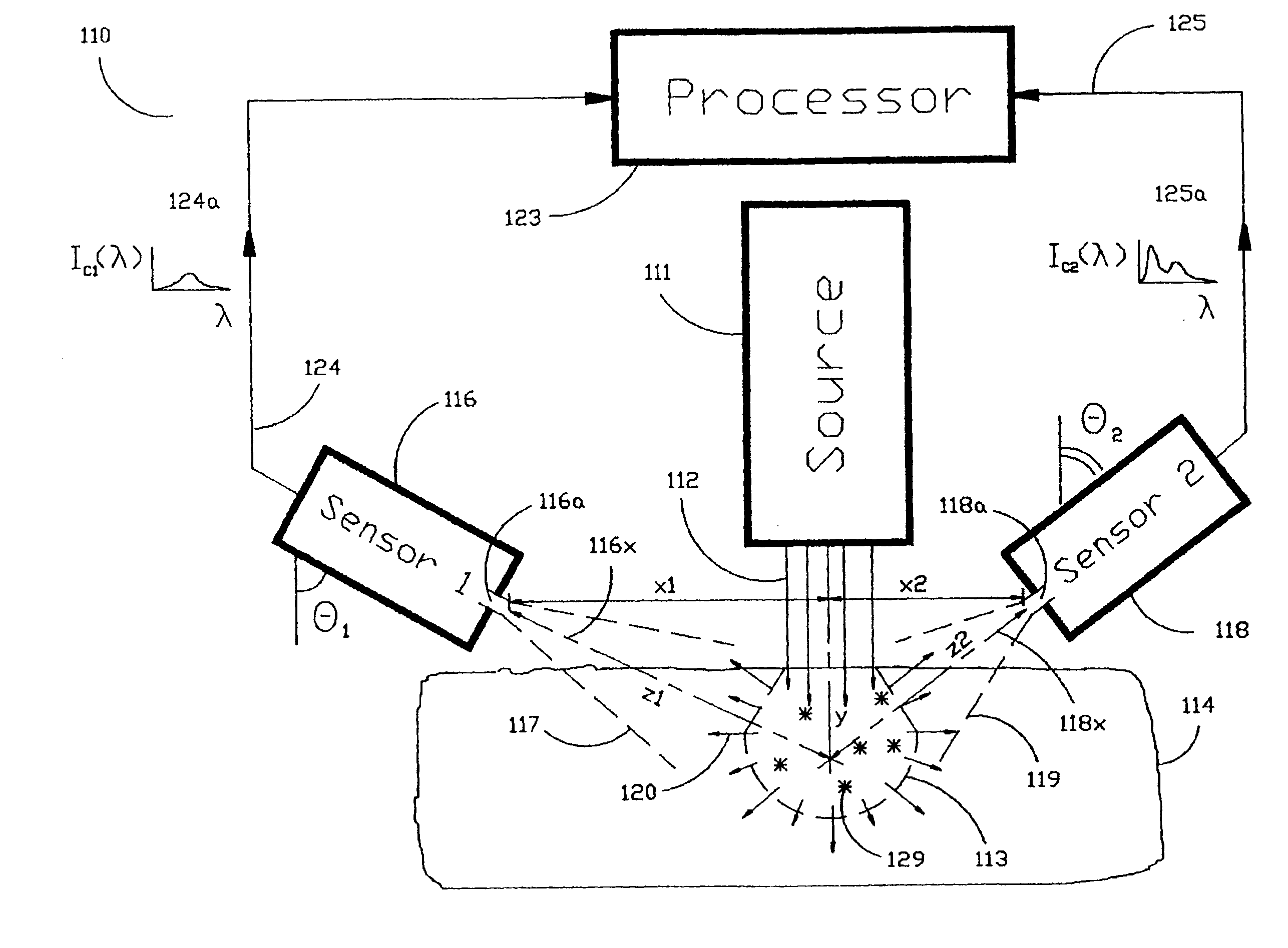
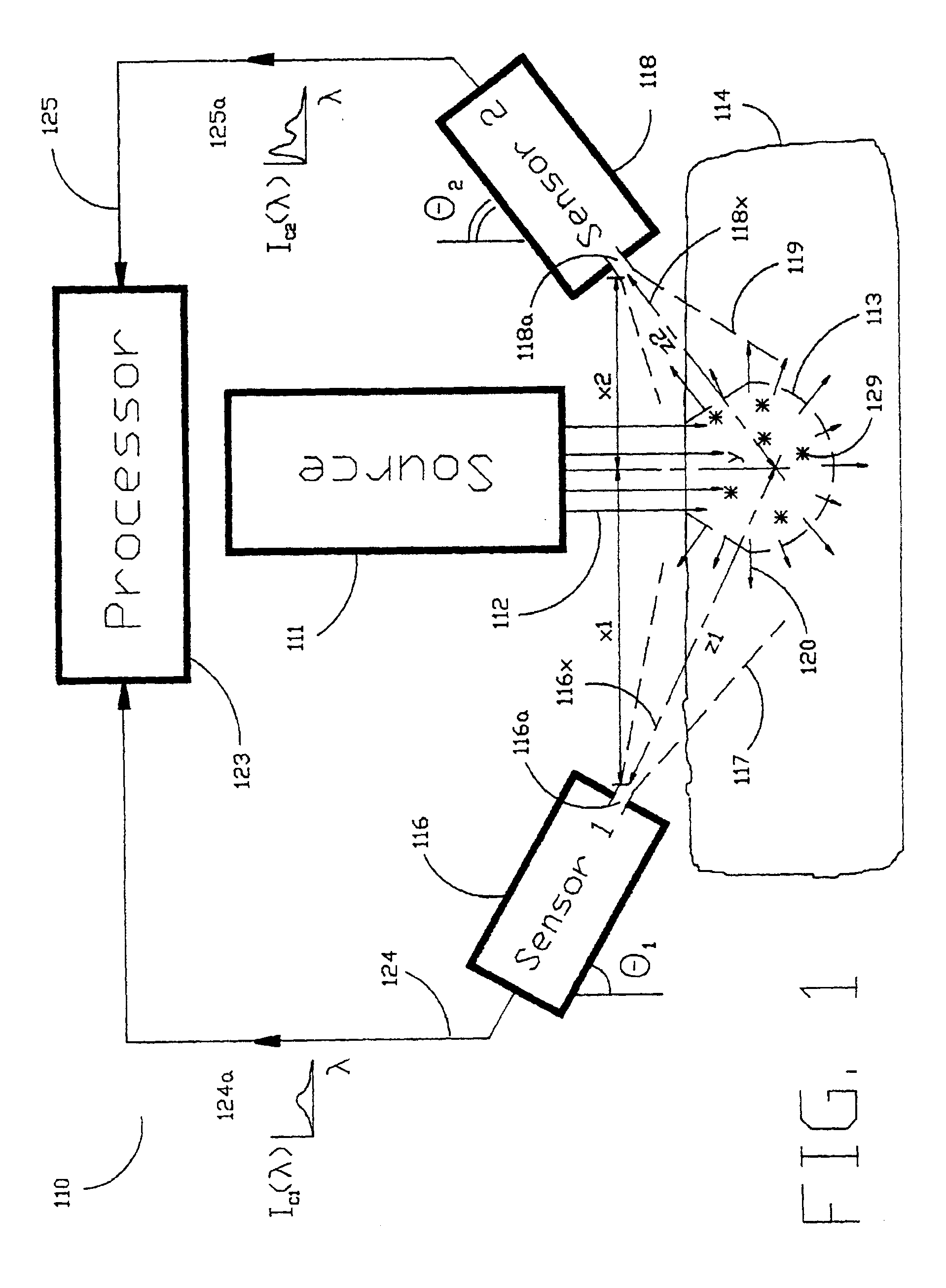
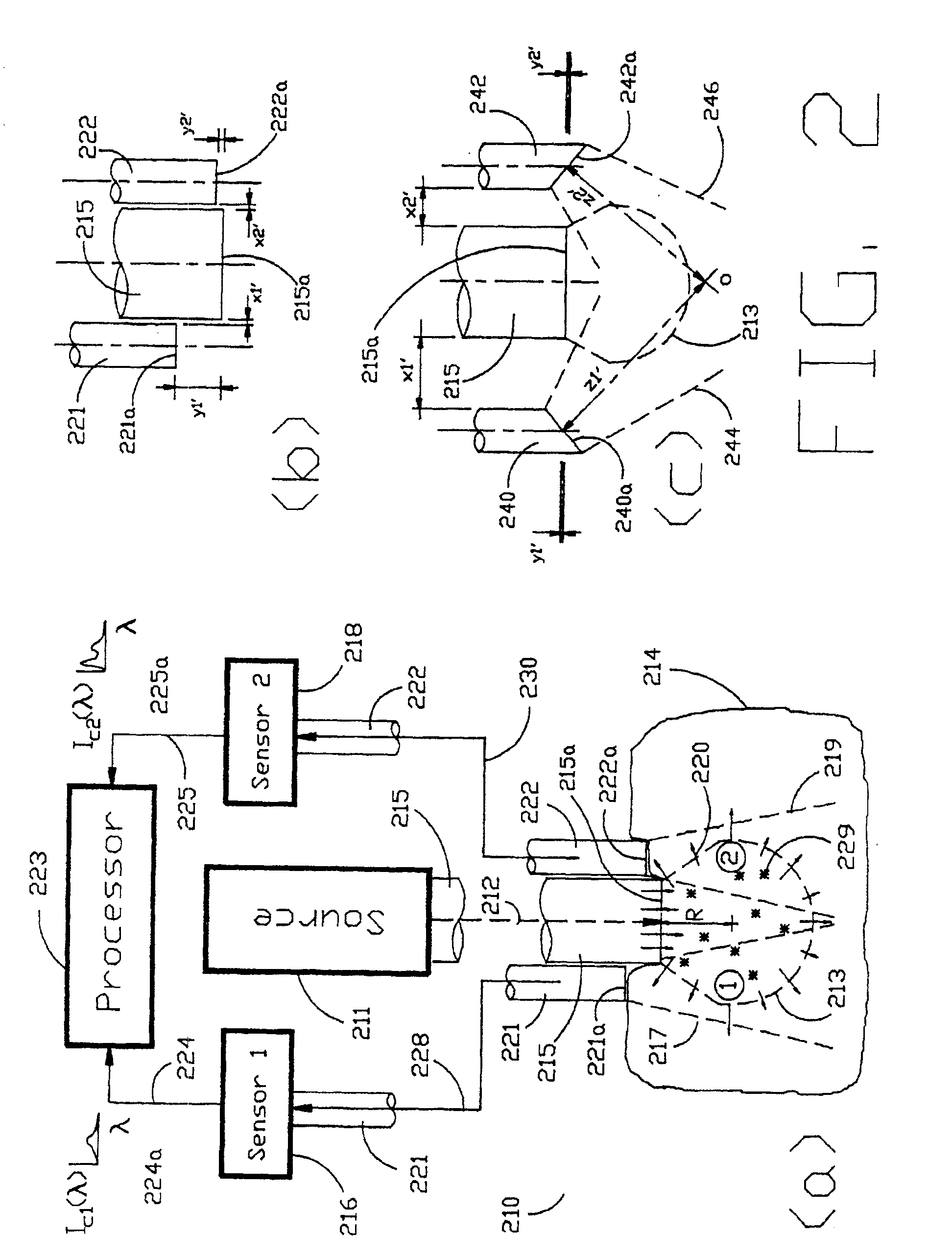
[0040]As shown in the exemplary drawings and, in particular, FIG. 1 thereof, the present invention is embodied in a spectroscopic system 110 and related method for measuring the attenuation and / or optical rotation caused by a sample 114. The spectroscopic system 110 shown in FIG. 1, includes a source 111 that produces radiation 112, which is directed at a sample volume 113 within the sample 114. The source 111 is preferably a laser and the radiation 112 is preferably monochromatic ultraviolet (UV), visible or infrared (IR) radiation 112. Nevertheless, the source 111 can be selected to produce other types of radiation, such as broadband or polarized radiation, useful for a particular application. The spectroscopic system 110 further includes a first sensor 116 displaced by a distance Z1 from the sample volume 113, and a second sensor 118 displaced by a distance Z2 from the sample volume 113, which are used to monitor return radiation 120 from the sample 114. In the preferred embodime...


PUM

PropertyMeasurementUnit
diameteraaaaaaaaaa
diameteraaaaaaaaaa
axial distance y2aaaaaaaaaa

Abstract

The Laser Induced Fluorescence Attenuation Spectroscopy (LIFAS) method and apparatus preferably include a source adapted to emit radiation that is directed at a sample volume in a sample to produce return light from the sample, such return light including modulated return light resulting from modulation by the sample, a first sensor, displaced by a first distance from the sample volume for monitoring the return light and generating a first signal indicative of the intensity of return light, a second sensor, displaced by a second distance from the sample volume, for monitoring the return light and generating a second signal indicative of the intensity of return light, and a processor associated with the first sensor and the second sensor and adapted to process the first and second signals so as to determine the modulation of the sample. The methods and devices of the inventions are particularly well-suited for determining the wavelength-dependent attenuation of a sample and using the attenuation to restore the intrinsic laser induced fluorescence of the sample. In turn, the attenuation and intrinsic laser induced fluorescence can be used to determined a characteristic of interest, such as the ischemic or hypoxic condition of biological tissue.

Description

BACKGROUND OF THE INVENTION[0001]The present invention is directed to methods and devices for determining a spectroscopic characteristic of a sample utilizing laser induced fluorescence attenuation spectroscopy (“LIFAS”). More particularly, the invention is directed to methods and devices for measurement of the wavelength-dependent attenuation of the sample and subsequent restoration of the intrinsic laser induced fluorescence (“LIF”) for physiological monitoring, biological tissue characterization and biochemical analysis.[0002]Conventionally, samples have been characterized by determining the attenuation and laser induced fluorescence (“LIF”). Once the attenuation and LIF of a sample have been determined, these spectroscopic properties can be utilized to determine a physical or physiological property of the sample. For example, the attenuation of a sample can be used to determine the concentrations of mixture components or turbidity of a fluid. Similarly, the LIF of a sample has b...

Claims


Application Information

Patent Timeline
Patent Type & Authority Patents(United States)
IPC IPC(8): G01N21/64A61B5/00A61B5/145A61B5/1455A61B10/00G01N21/27G01N21/49
CPCA61B5/0071A61B5/0075A61B5/0084A61B5/0086A61B5/1455A61B5/7267G01N21/49G01N21/6402G01N21/6428G01N21/6486G01N2021/6484G01N2201/06193
Inventor SHEHADA, RAMEZ E. N.MARMARELIS, VASILIS Z.GRUNDFEST, WARREN S.
Owner CEDARS SINAI MEDICAL CENT
Why Eureka
Try Eureka