
Optical lens for laser two-dimensional linear scanning

An optical lens and linear scanning technology, applied in the field of optical lens, can solve the problems of complex structure and high lens cost, and achieve the effect of simple lens structure, good marking quality and low processing cost

Inactive Publication Date: 2007-10-17
SUZHOU UNIV
View PDF5 Cites 0 Cited by
  • Summary
  • Abstract
  • Description
  • Claims
  • Application Information

AI Technical Summary

Problems solved by technology

At present, the working area of ​​the laser marking machine generally does not exceed 300×300mm 2 , the f-θ lens used is made of glass of different materials, and the structure is complex, and the cost of the lens is high

Method used


Image

  • Optical lens for laser two-dimensional linear scanning
  • Optical lens for laser two-dimensional linear scanning
  • Optical lens for laser two-dimensional linear scanning

Examples


Embodiment 1

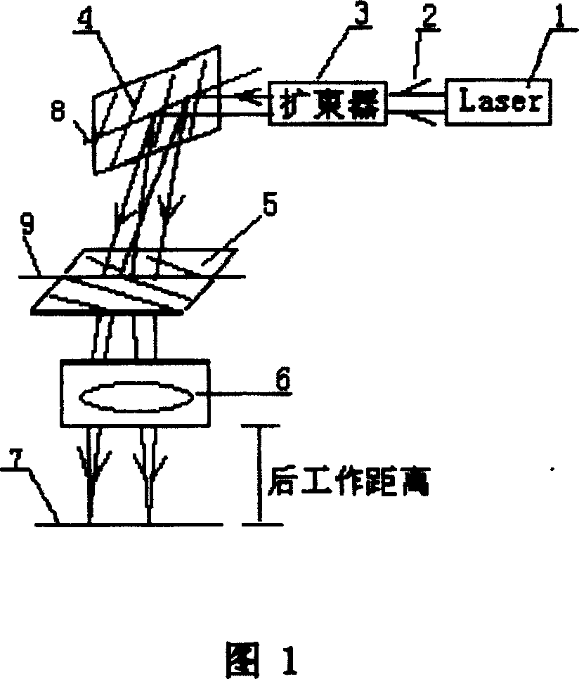
[0022] The technical solution of this embodiment is to provide an f-θ optical lens for a low-inertia vibrating mirror laser marking machine. The laser marking machine uses a YAG laser with a working wavelength of 1.064 μm. The optical system works on this near-infrared monochromatic light. The aperture diaphragm is located outside the optical system, that is, the X-scanning mirror [4] shown in Figure 1.

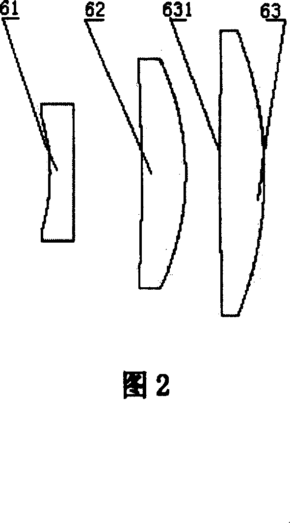
[0023] lens

[0024] The same colorless optical glass is used for the three lens materials, so there is no need to correct for chromatic aberration.

Embodiment 2

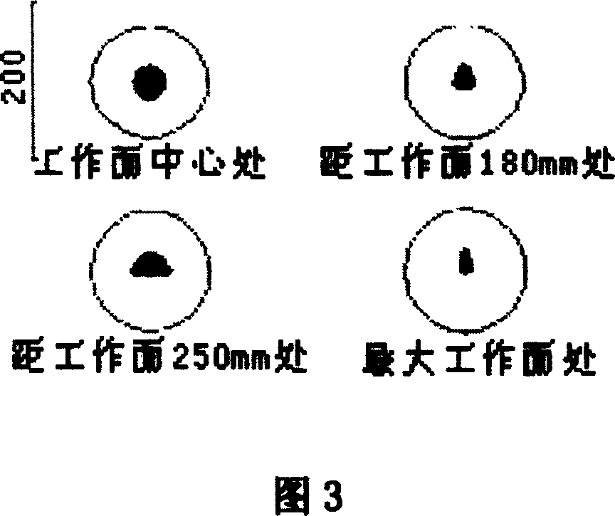
[0027] Referring to accompanying drawing 3, Fig. 3 is the ray tracing spot diagram that light passes through the optical system described in the present embodiment, namely the focusing situation of laser beam on workpiece surface, the circle at each field of view place in Fig. 3 represents Airy spot, by It can be seen that the spot diagrams of each field of view on the image plane fall within the Airy spot, indicating that the optical system has the focusing characteristics of the theoretical limit of diffraction.

[0028] The optical lens distortion curve figure described in the present embodiment is as shown in Figure 4, among the figure, the abscissa is the distortion value (unit %) relative to the f-θ relation, and the ordinate represents the normalized field of view, as seen in Figure 4 , the relative domain change is less than 0.5%, which not only makes the image height and field of view meet the f-θ linear relationship, but also does not affect the marking quality...


PUM


Abstract

The disclosed optical lens with f=theta is capable of focalizing laser beam onto working face, being suitable to prepare mark by laser and grave the mark. The optical lens is composed of three pieces of refraction lens. According to incidence direction of light ray, focal powers of lenses are negative, positive, and positive in sequence. Front two pieces of lens are bent toward incidence direction of light ray; and the front surface of the third lens is back on to incidence direction of light ray; glass material of the three pieces of lens is identical; and numeric area of refractive index as larger than and equal to 1.50, and less than and equal to 1.80. Working area can reach to 710 mm in diameter; and focusing performance reaches to diffraction limit. Advantages are: large working area, low cost, good quality of mark and focusing performance.

Description

technical field [0001] The invention relates to an optical lens for realizing laser two-dimensional linear scanning, in particular to an f-theta lens which focuses a laser beam on a working plane and is suitable for laser marking and marking. Background technique [0002] Laser marking is a form of laser scanning. It is an important application of laser in the field of processing. Compared with traditional marking methods such as stamping, etching, and machine engraving, it has no pollution, high resolution, and It has the advantages of permanent contact and marking, and is widely used in the production of laser anti-counterfeiting marks, lettering and surface decoration. [0003] Laser scanning technology includes high inertial scanning and low inertial scanning. Among them, high inertia scanning is a kind of mechanical scanning, which deflects the laser beam by rotating a prism, a plane mirror or a rotating polyhedron, but it realizes progressive sc...

Claims


Application Information

Patent Timeline
Patent Type & Authority Patents(China)
IPC IPC(8): G02B9/12G02B11/08G02B26/10B23K26/00B23K26/046B23K26/36
Inventor 沈为民季轶群余建军
Owner SUZHOU UNIV
Learn More