
Topside active optical device apparatus and method

A technology of optical devices and top surfaces, which is applied to laser parts, structure/shape of optical resonators, lasers, etc., can solve problems such as difficulties, unpopularity, complexity, etc., to improve product life, increase total output, The effect of cost reduction

Inactive Publication Date: 2007-12-12
CUFER ASSET LTD LLC
View PDF6 Cites 0 Cited by
  • Summary
  • Abstract
  • Description
  • Claims
  • Application Information

AI Technical Summary

Problems solved by technology

[0011] The complexity of this solution, the difficulty of overlay adhesion and maintaining the robustness of the overlay in cycles above operating temperatures, and the difficulty of obtaining reasonable yields make this solution unpopular for commercial applications

Method used


Image

  • Topside active optical device apparatus and method
  • Topside active optical device apparatus and method
  • Topside active optical device apparatus and method

Examples


example 1

[0269] In this example, the process part, the combination of joining materials (such as solder metal), melting point and attachment temperature are shown in Table 4:

[0270] Table 4

[0271]

craft

Material

Material

melting point

attach

temperature

Attaching Optics to Electronic ICs

20%Au / 80%Sn

280℃

310℃

Attach the IC to the package

95%Sn / 5%Sb

240℃

270℃

Attaching the package to the printed circuit board

63%Sn / 37%Pb

180℃

210℃

[0272] In this example, the first part of the process begins with the attachment of the optics to the integrated circuit (IC). This is done with the material with the highest melting point (in this case Au20% / Sn80% with a melting point of 280° C.). The interconnected joints are brought together and the temperature is raised above the melting point to melt the solder. The components to be joined are then cooled below the melting point ...

example 2

[0277] In this example, a similar transceiver is fabricated using a similar process, except that two optical chips (i.e., a laser chip and a photodetector chip) share a common chip and use a thermally active non-conductive melting temperature of 230°C and a curing temperature of 230°C. °C glue attaches an additional component used to align optical fibers and optics beyond the electronic chip. As a result the process is changed so that the attachment step of the components requiring adhesive is performed before the module is attached to the printed circuit board. The steps and materials included in the process are shown in Table 5.

[0278] table 5

[0279] craft

Material

material melting point

Attachment temperature

Attaching Optical IC to Electronic IC

20%Au / 80%Sn

280℃

310℃

Attach the IC to the package

95%Sn / 5%Sb

240℃

260℃

Attaching the Alignment Sheet to the Package

hot glue

230℃

230℃

...


PUM


Abstract

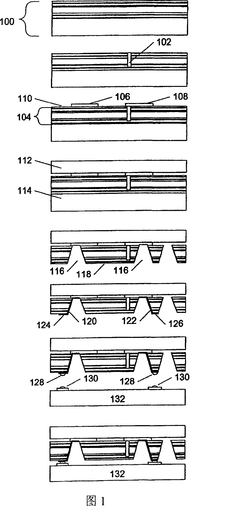
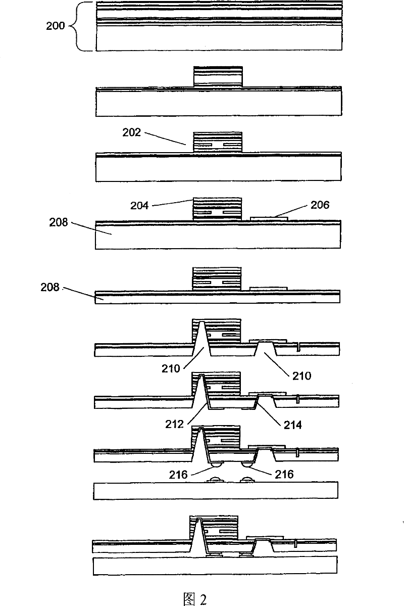
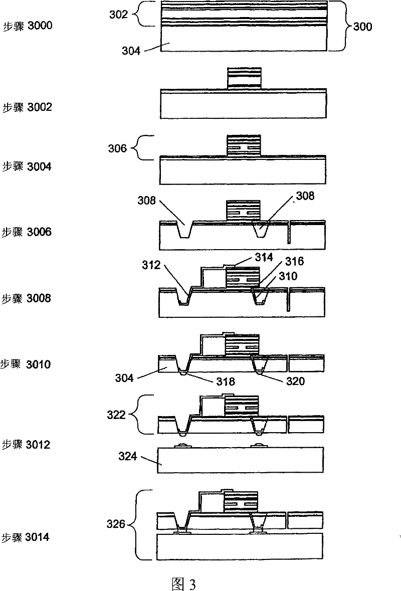
A method of integrating a topside optical device, having electrical contacts on a top side, with an electronic chip having electrical contacts on a connection side, involves creating a trench, defined by a wall, from the top side of a wafer containing the topside optical device into a substrate of the wafer, making a portion of the wall conductive by applying a conductive material to the portion; and thinning the substrate to expose the conductive material.

Description

[0001] Cross References to Related Applications [0002] This application claims priority under 35 USC 119(e)(l) to US Provisional Patents Serial Nos. 60 / 365,988 and 60 / 366,032, filed March 19, 2002. [0003] This application is also a continuation-in-part of commonly assigned US Patent Application Serial Nos. 09 / 896,189, 09 / 897,160, 09 / 896,983, 09 / 897,158 and 09 / 896,655, filed June 29, 2001. Background technique [0004] It is pre-set here that the reference signs are identified by #1-#2, where #1 is the label of the figure, and #2 is the item number in the figure. For example, 23-114 refers to item 114 in FIG. 23 . [0005] A top-emitting / handling device is an optical device that is oriented away from the wafer substrate on which the device is formed (ie, contains the optical device). Bottom (or back) emitting / processing devices have the optics themselves oriented towards the substrate. [0006] Top-side transmit / receive devices are a common device configuration used in t...

Claims


Application Information

Patent Timeline
Patent Type & Authority Patents(China)
IPC IPC(8): H01L21/00H01L23/48H01L29/40H01L33/00H01L33/10H01L33/20H01S3/08H01S5/00H01S5/02H01S5/183H04B10/04
CPCH01L31/035281H01S5/0207H01L2924/10253H01S5/183H01S5/0425H01L2924/01322Y02E10/50H01S5/02276H01S5/02272H01S5/0422H01L21/76898H01L31/022425H01L33/0079H01L2224/48227H01L33/105H01L2924/30107H01L2924/3025H01L2924/3011H01L33/20H01L2924/1461H01L2224/48091H01L2224/45014H01L2924/00014H01S5/04257H01S2301/176H01S5/423H01L33/0093H01S5/0237H01S5/02345H01L2924/00H01L2924/206H01S5/10
Inventor 汤姆·发斯卡格雷格·杜德夫
Owner CUFER ASSET LTD LLC
Learn More