
Substrate cleaning apparatus and method

A technology for cleaning devices and substrates, applied to discharge tubes, electrical components, plasma, etc., can solve problems such as over-etching, and achieve the effect of preventing electrification

Active Publication Date: 2008-05-14
TOKYO ELECTRON LTD
View PDF4 Cites 0 Cited by
  • Summary
  • Abstract
  • Description
  • Claims
  • Application Information

AI Technical Summary

Problems solved by technology

For example, there is a problem of overetching due to excessive etching on the wafer surface

Method used


Image

  • Substrate cleaning apparatus and method
  • Substrate cleaning apparatus and method
  • Substrate cleaning apparatus and method

Examples


Embodiment

[0124] Next, examples of the present invention will be specifically described.

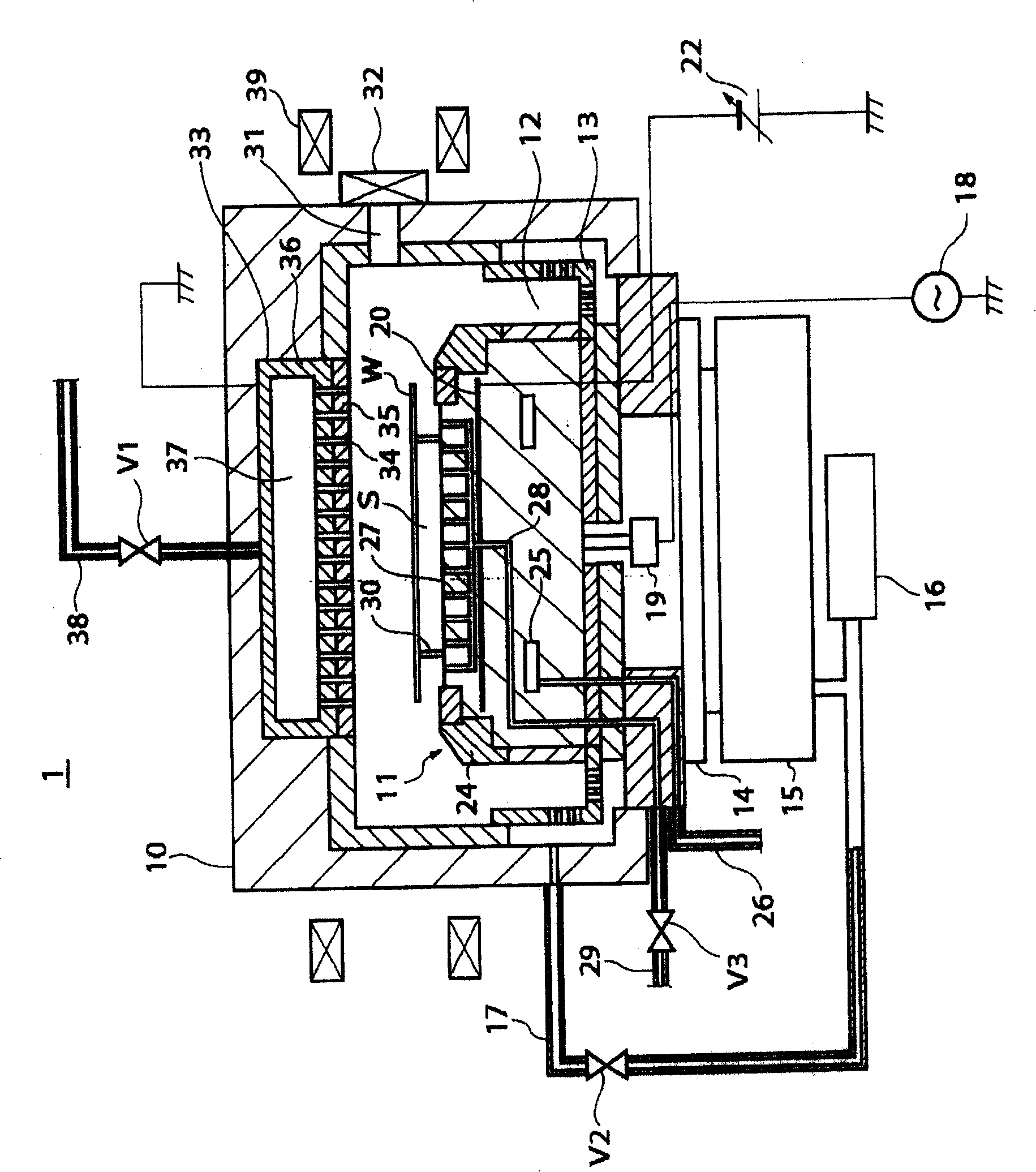
[0125] The following examples are carried out in the plasma processing apparatus 1 described above.

[0126] First, a wafer W on which a large amount of particles adheres to the back surface is prepared, and the wafer W is placed on the ejector pins 30 protruding from the susceptor 11 in the chamber 10 .

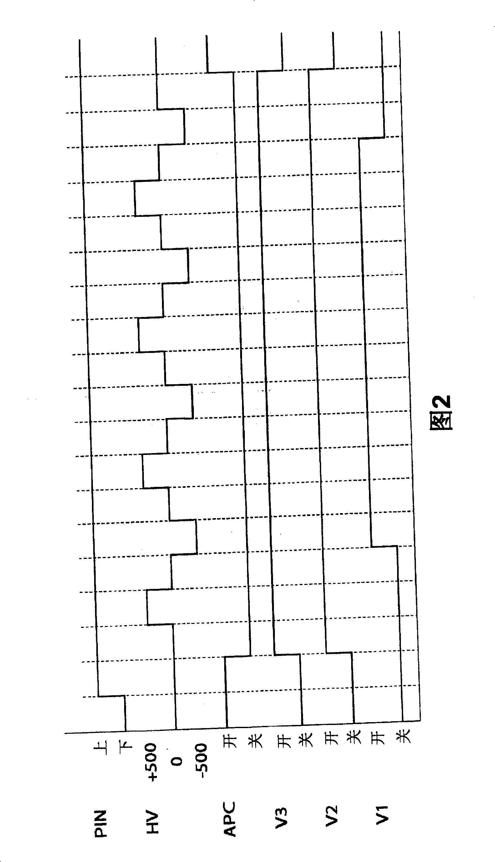
[0127] Then, after the chamber 10 is depressurized by the main discharge line, the APC 14 is closed, and the valve V2 of the exhaust pipe 17 and the valve V3 of the heat transfer gas supply pipe 29 are opened to stably exhaust the chamber 10. While feeding N from the heat transfer gas supply hole 27 2 The gas is ejected toward the back surface of the wafer W. As shown in FIG. Thereby, while keeping the inside of the chamber 10 at 6.65×10 3 Pa (50 torr) or more, while generating a viscous flow in the space S.

[0128] Next, open valve V1 with a flow rate of 7.0×10 4 SCCM put N 2 Gas is intr...


PUM


Abstract

A substrate cleaning apparatus includes a chamber for accommodating a substrate; a mounting table, disposed in the chamber, for mounting thereon the substrate; an electrode disposed in the mounting table, the substrate being attracted and held on the mounting table as a voltage is applied to the electrode; an exhaust unit for exhausting the inside of the chamber; a separating unit for separating the mounting table and the substrate to form a space therebetween; and a gas supply unit for supplying a gas into the space. While the space is formed, voltages of different polarities are alternately applied to the electrode, the gas supply unit supplies a gas into the space and the exhaust unit exhausts the inside of the chamber. The substrate cleaning apparatus further includes a gas introduction unit for introducing a gas into the chamber while the chamber is depressurized and the space is formed.

Description

technical field [0001] The present invention relates to a substrate cleaning device and a substrate cleaning method, and more particularly, to a substrate cleaning device and a substrate cleaning method for removing foreign matter adhering to the back surface of a substrate subjected to plasma treatment. Background technique [0002] Generally, in the manufacturing process of a semiconductor device, a semiconductor wafer (hereinafter referred to as "wafer") as an object to be processed is subjected to plasma processing (hereinafter referred to as "wafer") such as etching or sputtering, CVD (chemical vapor phase growth), etc. plasma treatment'). [0003] For example, as shown in FIG. 8, a plasma processing apparatus 80 for performing an etching process includes a cylindrical container 81 for accommodating wafers, which is arranged inside the cylindrical container 81 as a carrier for placing wafers. The base 82 of the stage is opposed to the surface on which the wafer is plac...

Claims


Application Information

Patent Timeline
Patent Type & Authority Patents(China)
IPC IPC(8): H01L21/302H05H1/46H01L21/304
CPCH01J37/32082H01J37/3266H01J37/32834H01L21/02057H01L21/0209H01L21/67017
Inventor 守屋刚中山博之
Owner TOKYO ELECTRON LTD
Learn More