Sealed oil tank liquid level transmitter
A liquid level transmitter and oil tank technology, applied in the field of sensor application, can solve the problems of not meeting the needs of oil fields, high cost, high price, and solve the problems of automatic monitoring and real-time measurement, low cost and wide measurement range. Effect
- Summary
- Abstract
- Description
- Claims
- Application Information
AI Technical Summary
Problems solved by technology
Method used
Image

Examples
specific Embodiment approach
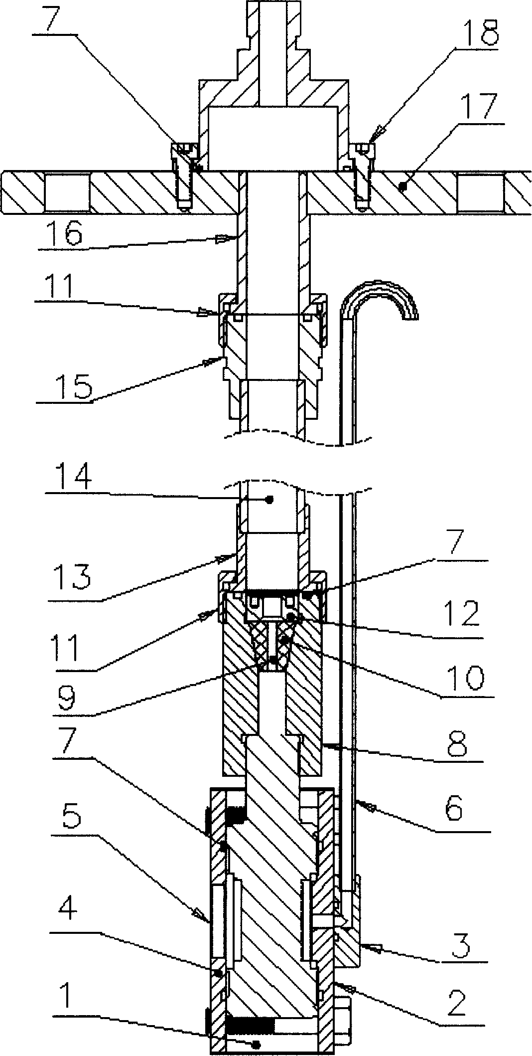
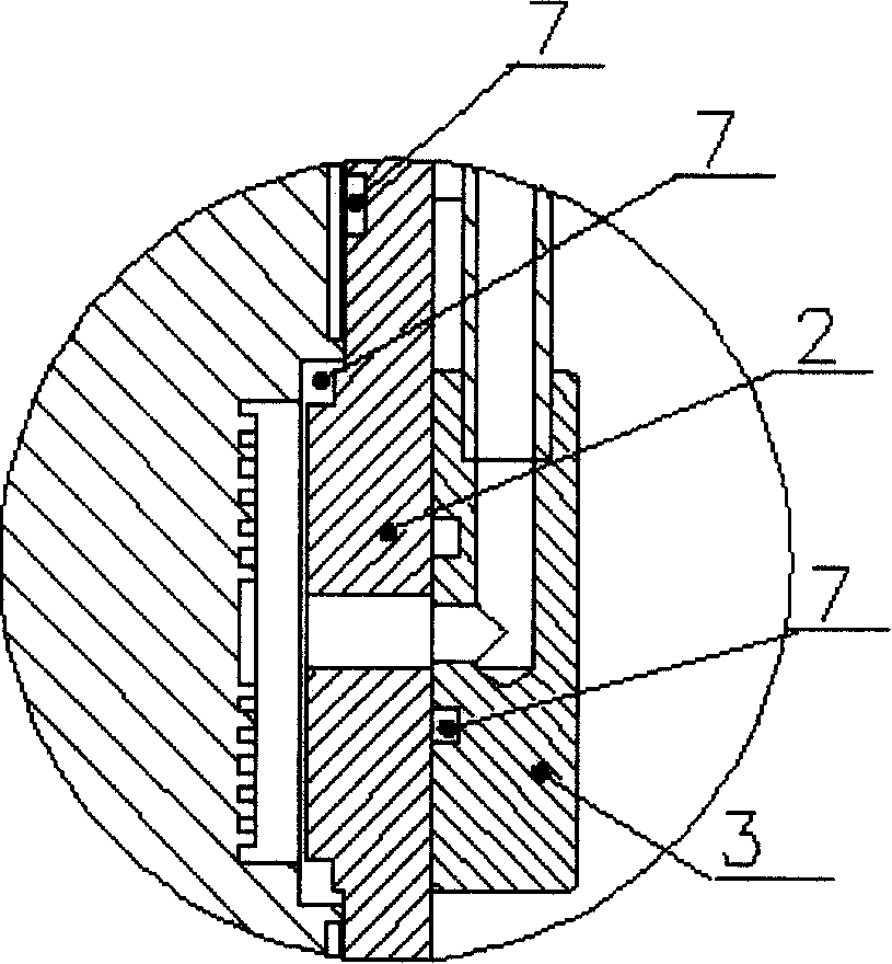
[0031]A liquid level transmitter for a sealed oil tank, comprising a sensor housing 1, a main splint 2, an air outlet plate 3, an auxiliary splint 4, a round hole 5 in the auxiliary splint, a vent pipe 6, a lead wire 9 on the sensor, a wire protection pipe 14, Flange 17. The sensor is fixed in the sensor housing 1, the lower end of the vent pipe 6 is fastened on the air outlet plate 3, and the upper end extends above the measurement liquid level, the lower end of the line protection tube 14 is connected to the sensor through the sealing joint 8, and the upper end is connected to the sensor through the flange joint 16. The flange 17 is connected, and the lead-out wire 9 on the sensor is drawn out through the wire protection tube 14 . The sensor is a differential pressure sensor. The pressure sensing surfaces on both sides of the differential pressure sensor respectively feel the air pressure above the measured liquid level and the pressure at the measured liquid level point in ...
Embodiment
[0032] Embodiment: Through the integration technology of signal processing circuits such as thick-film hybrid integrated circuit or flexible circuit board integration, the linear adjustment, zero point adjustment, full-scale adjustment, and temperature compensation adjustment circuits of the pressure-sensitive element are integrated on the pressure-sensitive element. Integral, so that the output of the sensor lead wire 9 is a standard current or voltage signal, realizing a long-distance transmission of the signal of the liquid level transmitter of the sealed oil tank.
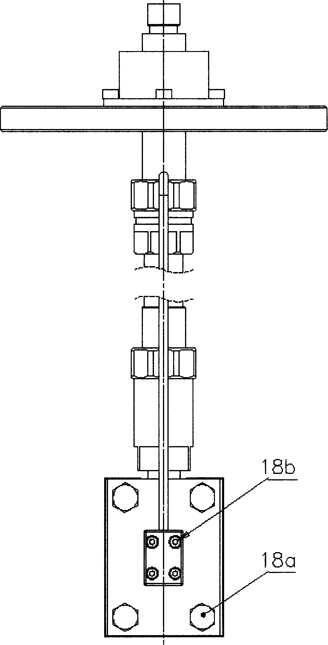
[0033] The sensor housing 1 is a rectangular cavity structure, which is composed of the main splint 2 and the auxiliary splint 4. The outer hexagonal screw 18a is used as a positioning part to clamp and fix the sensor, and the sealing ring 7 is compacted and sealed, and the pressure on both sides of the sensor is exposed. surface to protect the sensor components and make the sensor feel differential pressure. T...
PUM
 Abstract
Description
Claims
Application Information
PatSnap Eureka turns technology decisions into work you can execute. Powered by our Innovation Knowledge Graph, it runs expert workflows across engineering, life sciences, materials and intellectual property. Get your review-ready output in minutes.


