Phase detetor and phase detecting method

A phase detector and phase detection technology, which can be used in circuits that oscillate independently of each other, automatic power control, digital transmission systems, etc., and can solve problems such as expensive and complex products.

Inactive Publication Date: 2008-07-16
GIGA APS
View PDF2 Cites 2 Cited by
  • Summary
  • Abstract
  • Description
  • Claims
  • Application Information

AI Technical Summary

Problems solved by technology

Such processing requires prior knowledge of the bit frequency and produces an expensive and complex product

Method used


Image

  • Phase detetor and phase detecting method
  • Phase detetor and phase detecting method
  • Phase detetor and phase detecting method

Examples


Embodiment Construction

[0028] The circuits disclosed below are preferably integrated in one or several integrated circuits. The high speed operation required by the position maintaining circuit, logic gates and circuit blocks are best implemented in CML logic with bipolar transistors. The best processing is the 0.4 μm bipolar processing suitable for digital circuits operating in the frequency range from about 622 MHz to 10 GHz. NPN transistors provided by this process have f of about 25GHz T value. Additionally, commercially available 0.13-0.25 μm CMOS processes with sufficiently fast transistors can be applied in some embodiments of the present invention, for example in circuits operating at low system frequencies.

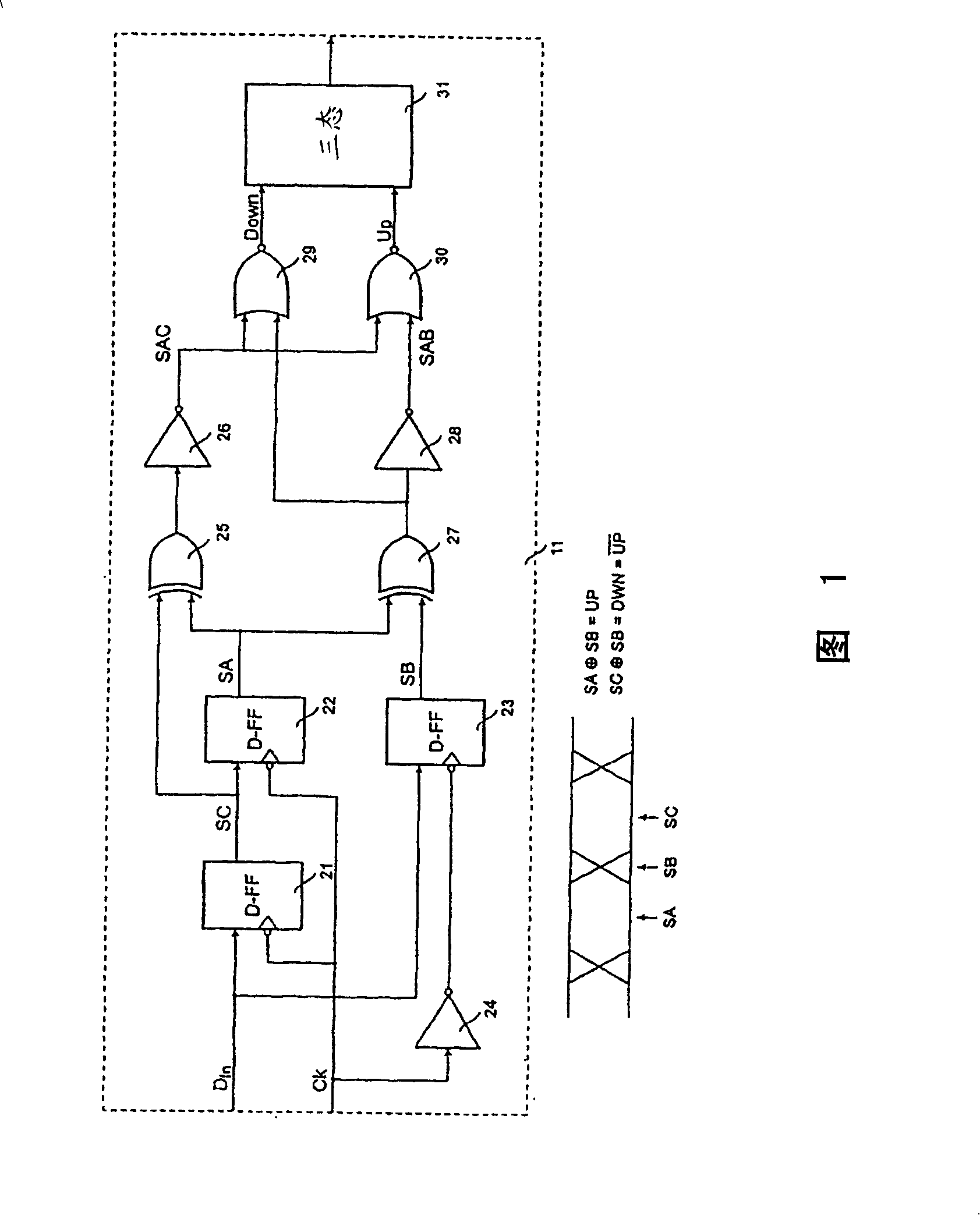
[0029] The basic operation of the pulse phase detector will be explained with reference to FIG. 1 , which shows an example of a pulse phase detector 11 . The phase detector 11 compares the clock signal C k and data signal D in A binary output signal is provided in response to a ph...


PUM


Abstract

The present invention relates to a phase detector and utilisation of the phase detector for synchronisation of a digital signal with a clock signal. It is an object of the present invention to provide a phase detector with improved characteristics including jitter tolerance and jitter transfer. It is another object of the invention to provide a phase detector that generates an output signal that, when used as a control signal in a phase or frequency locked loop, keeps the gain of the control loop substantially invariant to the transition density of the phase detector input signals. According to the invention, these aspects are fulfilled by provision of a phase detector for detection of a phase difference between a first signal and a second signal. The phase detector comprises a first logic circuit for detection of a data transition of the first signal and a second logic circuit that generates a logic output signal of a first logic value upon detection of a data transition of the first signal if a transition of the second signal occurs before the transition of the first signal and of a second logic value if the transition of the second signal occurs after the transition of the first signal.

Description

technical field [0001] The present invention relates to phase detectors and the use of phase detectors for the synchronization of digital data signals and clock signals, for example in clock and data recovery circuits. Background technique [0002] When digital data is transmitted at high data rates, such as over optical transmission lines, it is typically necessary to synchronize the transmitted data bits with a clock signal. Typically, the clock signal is generated from the data signal received in the clock and data recovery circuit. Noise immunity is a key characteristic of clock and data recovery circuits. [0003] ITU-T has specific fluctuation parameters determined in the frequency domain. The fluctuation tolerance of a receiving device is defined as a sinusoidal peak-to-peak phase modulation that produces an optical loss of 1 dB. [0004] For example, white noise is added to the input signal when representing clock and data recovery components. By varying the sign...

Claims


Application Information

Patent Timeline
Patent Type & Authority Patents(China)
IPC IPC(8): H03K19/21H03L7/00H03D13/00H03L7/089H04L7/033
CPCH03L7/089H03D13/004H04L7/033
Inventor H·I·约翰森H·利斯达尔B·克里斯藤森
Owner GIGA APS
Why Eureka
Try Eureka