
Apparatus and method for realizing switch magnetic resistance motor electronic gear function

A technology of switched reluctance motors and electronic gears, which is applied in electromechanical devices, emergency protection circuit devices, electronic commutators, etc., and can solve problems such as the non-linear characteristics of switched reluctance motors, difficulty in suppressing torque ripple, and small number of pulses , to achieve the effect of improving dynamic and static performance, improving control accuracy and reducing the complexity of mechanical structure

Inactive Publication Date: 2009-01-07
HEBEI UNIV OF TECH
View PDF3 Cites 1 Cited by
  • Summary
  • Abstract
  • Description
  • Claims
  • Application Information

AI Technical Summary

Problems solved by technology

[0003] The object of the present invention is to provide a device and method for realizing the electronic gear function of a switched reluctance motor. In view of the above situation, it solves the problem that the non-linear characteristics and torque ripple of the switched reluctance motor are difficult to suppress and the number of position pulses per revolution is small. , and then find out the function realization method of the electronic gear of the switched reluctance motor with a small number of position pulses per circle, and develop the function realization system of the electronic gear of the switched reluctance motor

Method used


Image

  • Apparatus and method for realizing switch magnetic resistance motor electronic gear function
  • Apparatus and method for realizing switch magnetic resistance motor electronic gear function
  • Apparatus and method for realizing switch magnetic resistance motor electronic gear function

Examples


Embodiment Construction

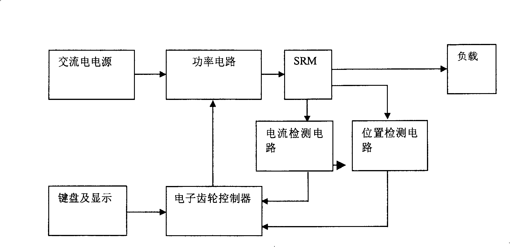
[0019] figure 1 As shown, the switching reluctance motor electronic gear function realization method and device of the present invention mainly include: switched reluctance motor electronic gear controller, power circuit, keyboard and display circuit, current detection circuit and position detection circuit and switched reluctance motor . The connection method is: both the switched reluctance motor and the electronic gear controller of the switched reluctance motor are connected with the power circuit, the switched reluctance motor is connected with the electronic gear controller of the switched reluctance motor, and the keyboard and display circuit are connected with the electronic gear controller of the switched reluctance motor. The gear controller is connected. The current detection circuit is respectively connected with the electronic gear controller, the position detection circuit and the switched reluctance motor, and the position detection circuit is connected with th...


PUM


Abstract

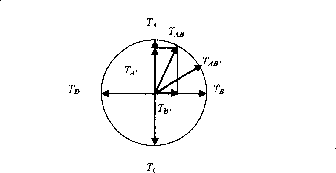
A method for realizing function of electronic gear on switching reluctance motor includes connecting said motor separately to servo controller of said motor, electronic gear circuit and power circuit; connecting electronic gear controller of said motor to power circuit, keyboard and display circuit; using said motor rotator position detected out by detection circuit and teeth number ratio set by client in advance to carry out vector addition on motor torque for realizing function of electronic gear. The device for realizing said method is also disclosed.

Description

technical field [0001] The invention belongs to a method and a device for implementing an electronic gear by using an electric transmission control system instead of a mechanical transmission chain, in particular to a device and a method for realizing the electronic gear function of a Switched Reluctance Motor (SRM for short). Background technique [0002] Gears are widely used in machinery, metallurgy, papermaking, and other industrial sectors due to their accurate transmission ratio, large transmission power, and stable transmission. However, in some application fields, gear transmission has defects such as large transmission error and difficulty in realizing distributed transmission ("Research and Application of Electronic Gear Box System", 2001.3 "Mechanical Design and Manufacturing Engineering"). For example, in the printing field, due to the transmission shaft The distortion and gear gap will affect the tension and overprint of the printing machine, which will directly...

Claims


Application Information

Patent Timeline
Patent Type & Authority Patents(China)
IPC IPC(8): H02P6/16H02P27/08H02K11/00H02H7/08H02P25/089H02P25/092
Inventor 孙鹤旭郑易董砚宋桂英王伟刘海涛
Owner HEBEI UNIV OF TECH
Learn More