Method for vacuum prification of material by self-rotation elevation tracked solar furnace

A technology of solar furnace and vacuum, which is applied in the direction of solar thermal devices, solar thermal power generation, chemical instruments and methods, etc., and can solve the problems of huge capital manufacturing process, large spot, and affecting the purification process, etc.

Inactive Publication Date: 2009-02-11
丰宁满族自治县应天光电技术有限公司
View PDF6 Cites 5 Cited by
  • Summary
  • Abstract
  • Description
  • Claims
  • Application Information

AI Technical Summary

Problems solved by technology

[0005] 1. The existing material purification process takes a long time, such as 5-12 hours; however, the time that can be used for solar energy material purification is only 5-8 hours a day, and the light intensity changes during this long period, and the temperature of the material is difficult Grasp, seriously affect the purification process, unable to formulate a process that can be industrialized
[0006] 2. The traditional solar furnace uses the secondary focusing method, and the second concentrator has a large aperture and a long focal length (such as the French Odeillo
[0007] The focal length of the parabolic mirror of a 1MW solar furnace is 18m), so the spot is large, which complicates the design of the heating reactor, and the vacuum container must be enlarged
If the vacuum container is made of transparent quartz, the wall thickness of the container must be increased when increasing the volume of the container, such as 6mm or more so that the container can withstand greater vacuum pressure, which will greatly increase the manufacturing cost of the reactor and make industrialization difficult. Reality
At the same time, increasing the wall thickness causes the quartz wall to absorb more light energy, which will soften the quartz wall due to high temperature, and will accelerate the damage of the container
[0008] At present, the traditional design of solar furnaces requires huge funds and complicated manufacturing processes, which greatly limits the feasibility of its popularization and industrialization.

Method used


Image

  • Method for vacuum prification of material by self-rotation elevation tracked solar furnace
  • Method for vacuum prification of material by self-rotation elevation tracked solar furnace
  • Method for vacuum prification of material by self-rotation elevation tracked solar furnace

Examples


Embodiment Construction

[0016] specific implementation plan

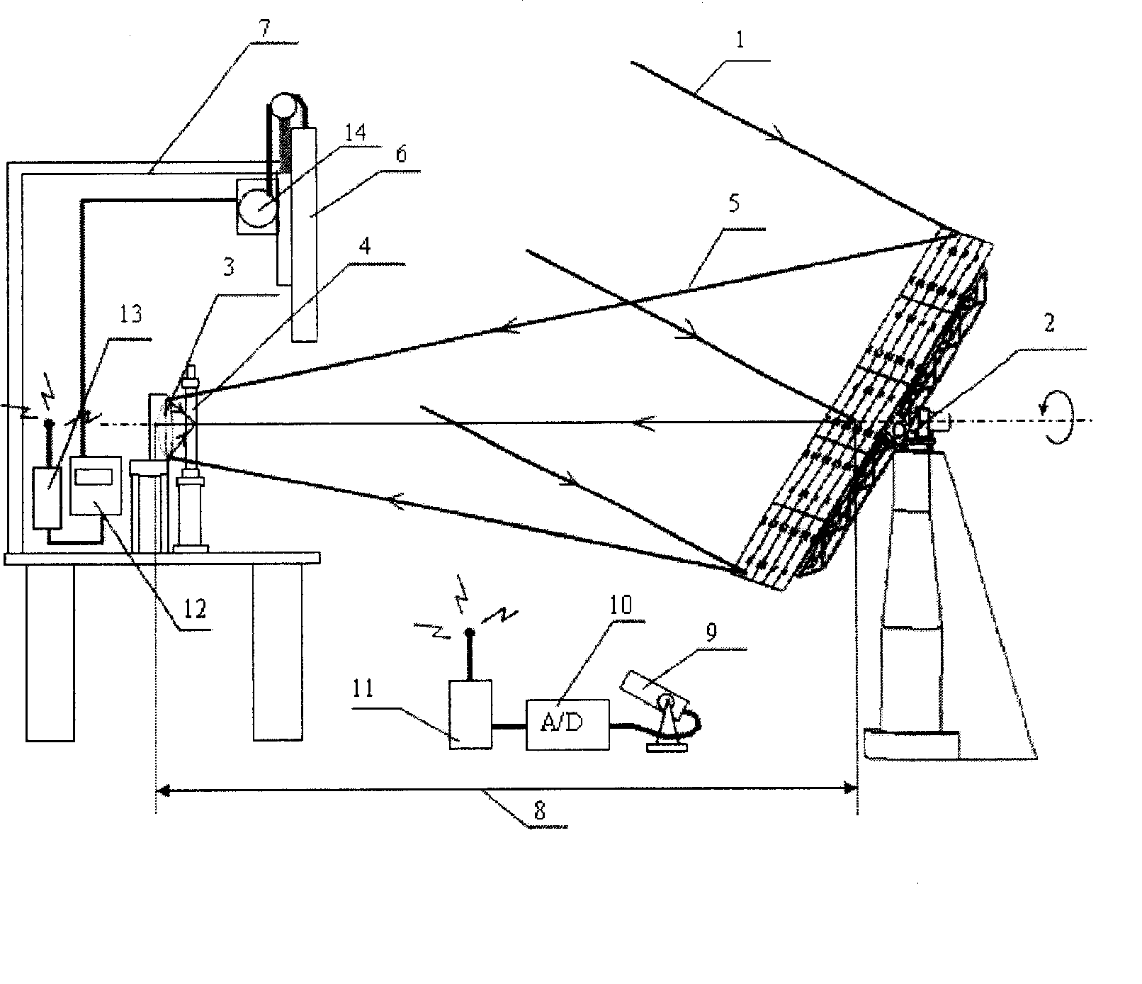
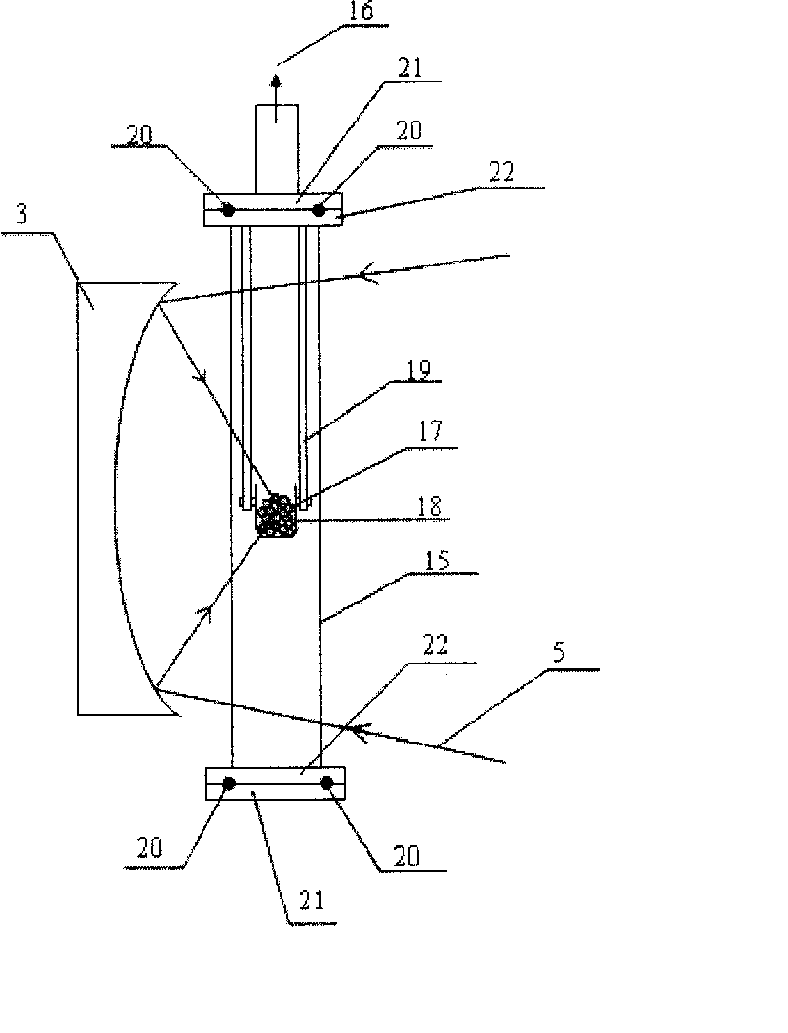
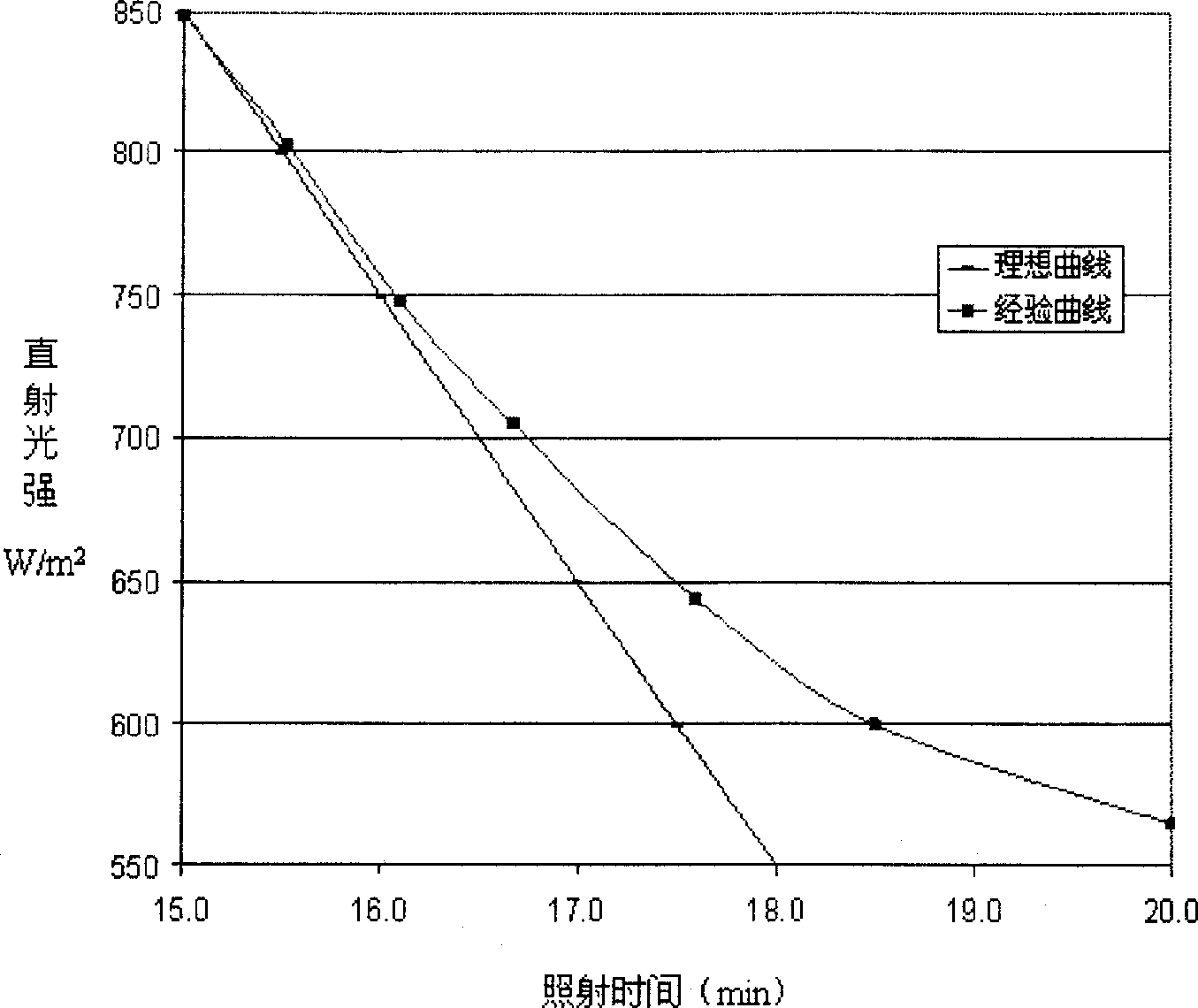
[0017] This scheme is an application example of the present invention. Below in conjunction with accompanying drawing and specific embodiment, the present invention will be described in further detail: principle structural diagram of the present invention is by Figure 1.1 and 1.2 Given that, the choice of exposure time relative to solar exposure is given by figure 2 give. Among them, the heliostat 2, which is tracked by the spin elevation angle, tracks the sun, and the lighting area of ​​the heliostat is 25m 2 , the target distance 8 of the heliostat is 18m, the heliostat reflects the incident sunlight 1 and focuses it to the spherical reflector 3 placed in the studio 7 at the same time, the diameter of the reflector is 60cm; the spherical reflector 3 will come from the heliostat The light 5 of the mirror is refocused, and its focal point is at the center of the high-purity quartz crucible 18. The capacity of the crucible is 80ml, and...


PUM


Abstract

This inventive process contains steps of: heating the raw material in crucible under vacuum condition by the irradiation from solar energy stove utilizing elevation angle tracing mode and matrix turning aberration correction method. After the content is heated and liquefied, the irradiation is contained to the content being heated up to boiled condition. Thorough agitation is proceeded to make the impurities being volatiled off in that vacuum condition. After a certain irradiation duration, the purity of the content reaches the target. Under the conditions of direct light intensity being more than 550 w / square meter, and the quantity of the content being less than 150 g, the typical irradiation duration is 15-20 min. the accurate irradiation duration for this inventive method can be obtained by searching the curved of light intensity curve. The raw materials being subject to this purification are: silicon, titanium, calcium, aluminium and the like. This invented method has many advantages than that of prior art method.

Description

technical field [0001] The present invention relates to a method for vacuum purification of materials, especially a device that tracks the sun, gathers sunlight at a high power, and uses the concentrated sunlight to generate high temperature to smelt materials under vacuum to achieve purification. effect method. Background technique [0002] The existing material vacuum purification technology, such as the purification technology of tantalum, involves heating the material in a vacuum until the material is liquefied, and the impurities contained in the liquefied material are volatilized in a vacuum. After a long heating time, the material’s The purity reaches the required index. The heating tools used in the aforementioned vacuum purification techniques include electron beam furnaces, electromagnetic furnaces and resistance furnaces. The method of electric heating has certain limitations to most materials, especially metal or semiconductor materials, mainly because the resi...

Claims


Application Information

Patent Timeline
Patent Type & Authority Patents(China)
IPC IPC(8): C01B33/037C22B9/04F27B17/00F24J2/00
CPCY02E10/40
Inventor 陈应天林晨星林文汉
Owner 丰宁满族自治县应天光电技术有限公司
Why Eureka
Try Eureka