
Resonance type micromirror grating scanning type laser projection display device

A resonant micromirror and raster scanning technology is applied in the direction of image reproducer, projection device, optics, etc. of projection devices to achieve the effect of reducing driving voltage requirements, reducing precision requirements, and reducing costs

Inactive Publication Date: 2009-04-29
SOUTHEAST UNIV
View PDF5 Cites 0 Cited by
  • Summary
  • Abstract
  • Description
  • Claims
  • Application Information

AI Technical Summary

Problems solved by technology

The second is to better reproduce natural colors. According to statistics, traditional displays using phosphors and light bulbs can only express 30% of the natural colors seen by the human eye, while laser displays can express 83%.

Method used


Image

  • Resonance type micromirror grating scanning type laser projection display device
  • Resonance type micromirror grating scanning type laser projection display device
  • Resonance type micromirror grating scanning type laser projection display device

Examples


Embodiment Construction

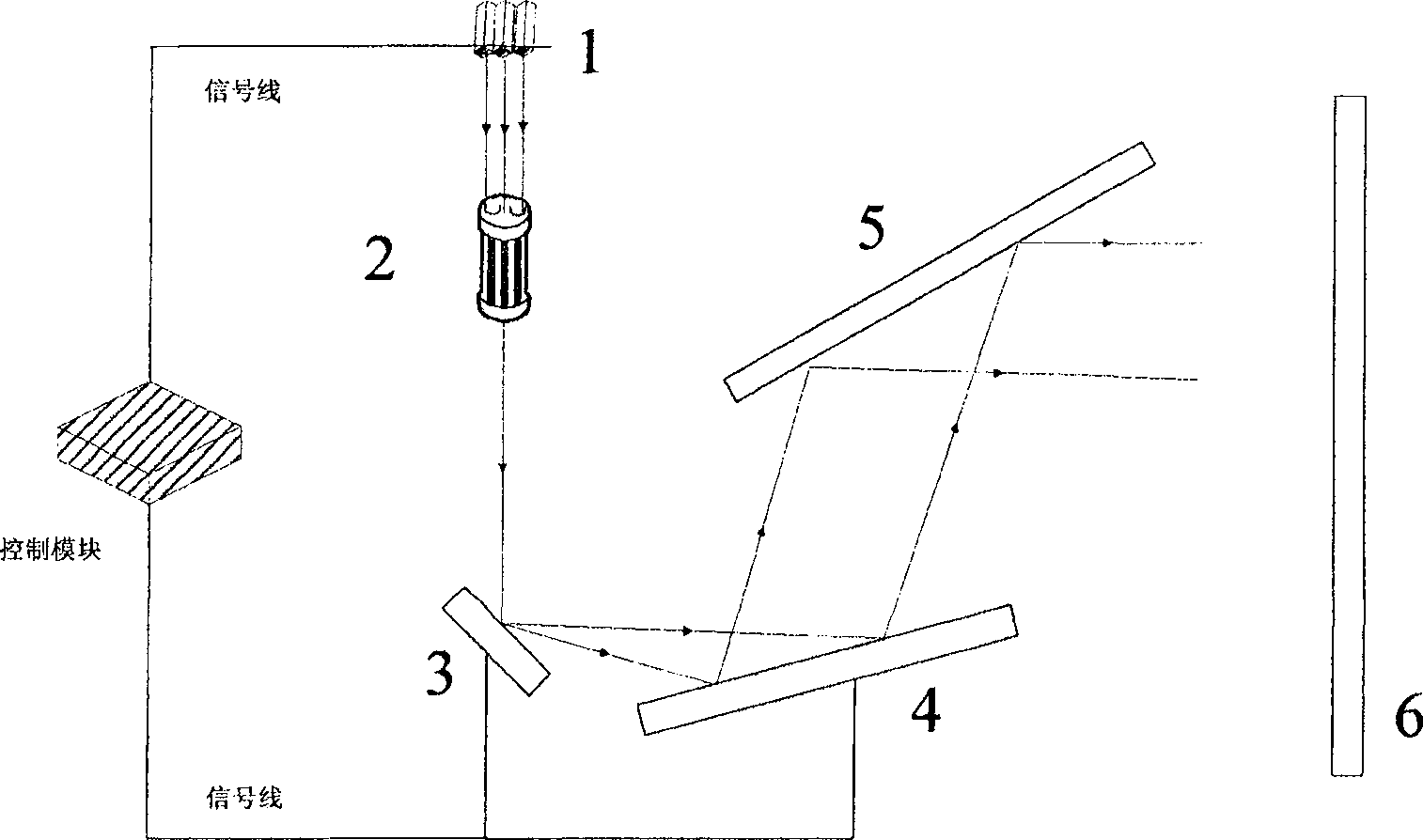
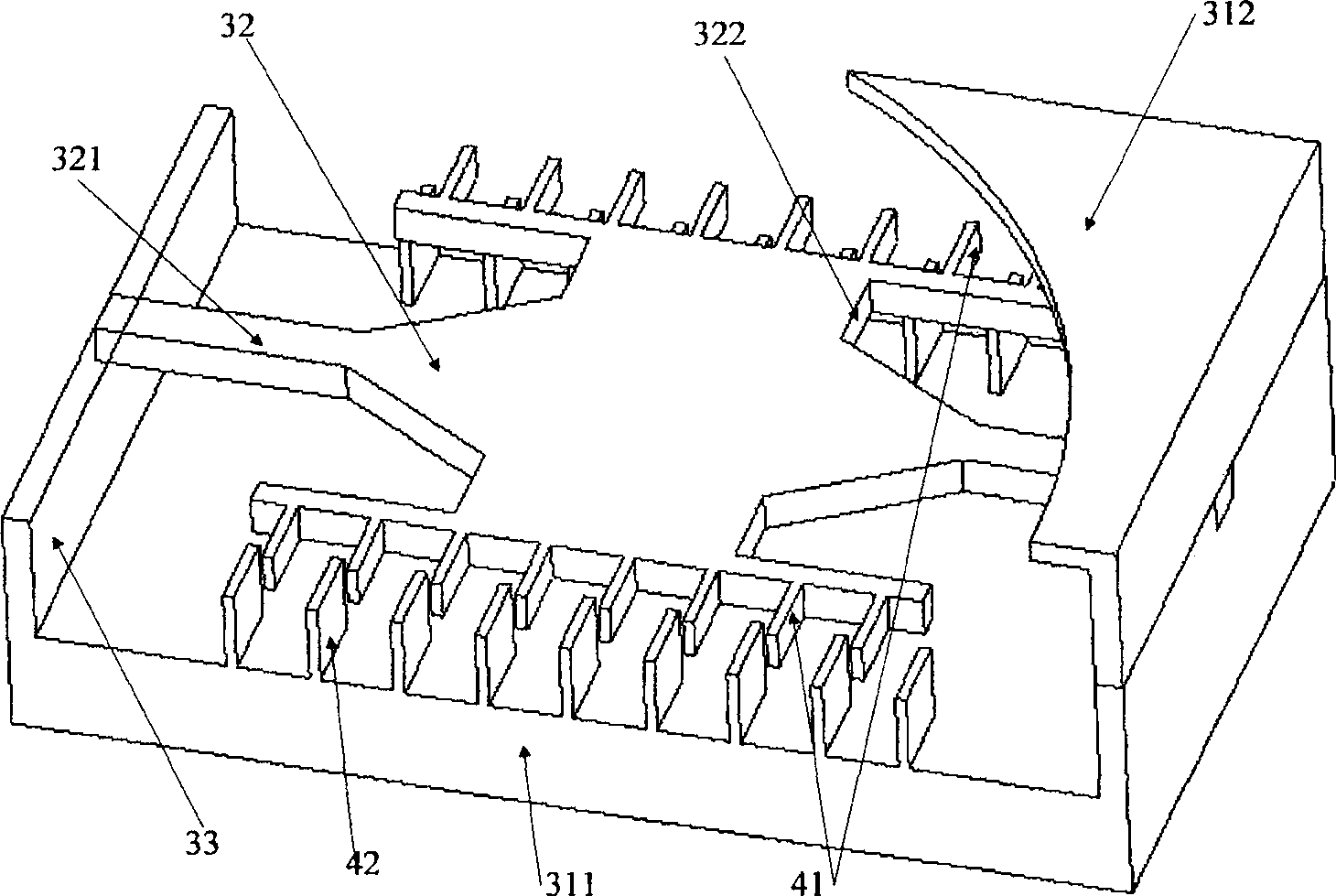
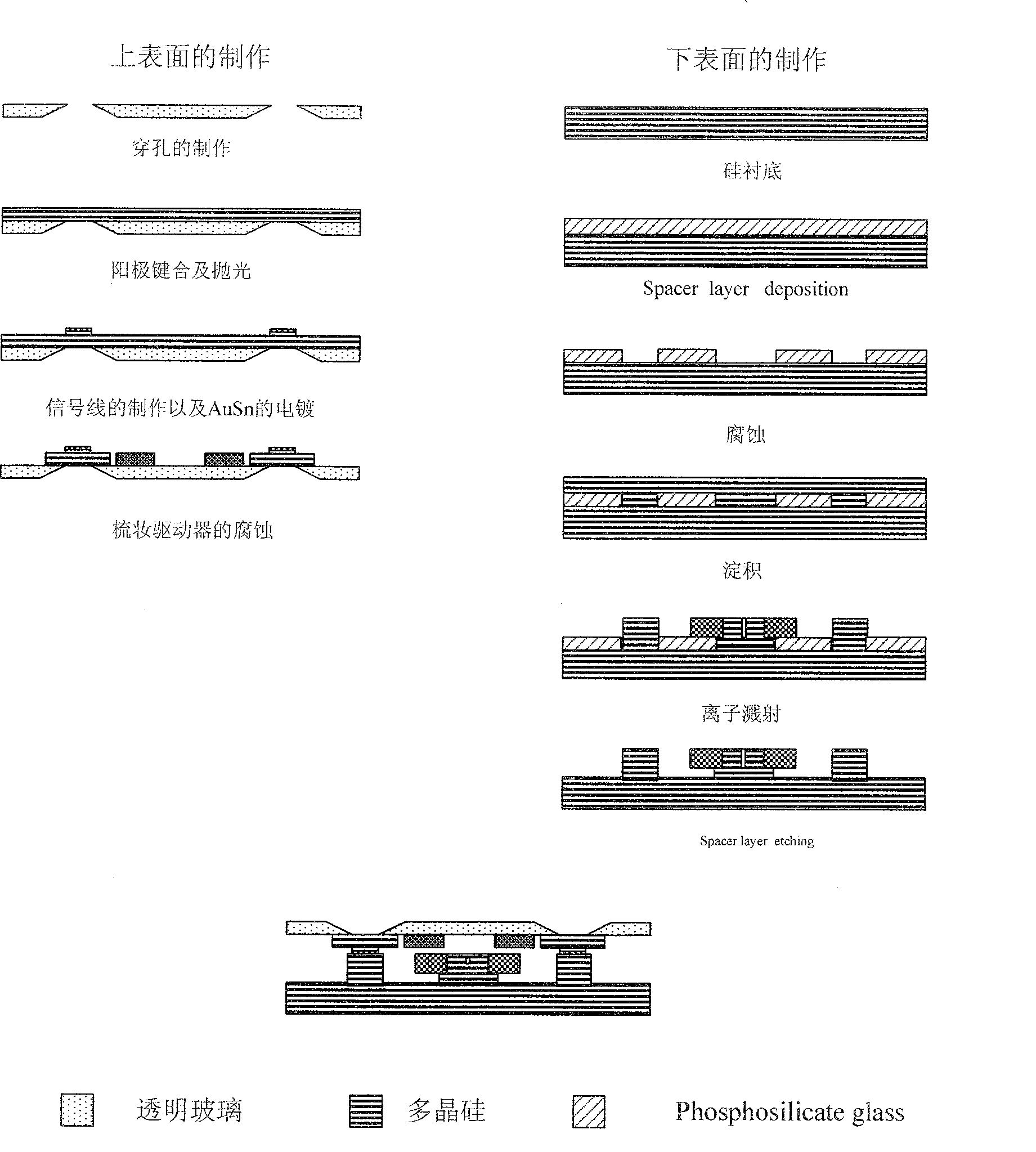
[0021] A resonant micromirror raster scanning laser projection display device, which consists of red, green, and blue lasers 1, an optical fiber color mixer 2, a scanning micromirror 3, a second reflector 4, a static mirror 5, and a screen 6. Red, green 1. The light emitted by the blue laser 1 is projected on the screen 6 through the optical fiber color mixer 2, the scanning micromirror 3, the second reflector 4 and the static mirror 5. The scanning micromirror 3 adopts a resonant scanning micromirror, and the resonant scanning micromirror The mirror includes: a lower substrate 311 and an upper light-transmitting plate 312, a mirror surface 32 and an electrostatic driver are arranged between the lower substrate 311 and the upper light-transmitting plate 312, and the upper light-transmitting plate 312 is positioned above the mirror surface 32, and a support is provided on the lower substrate 311 33. The mirror surface 32 is connected to the bracket 33 through the rotating arms 3...


PUM


Abstract

This invention provides a kind of laser projection display packing, which uses resonance microscope to reach grating scan. It is made up of a video-processing module, a control module, a resonance scan microscope, a laser machine, the modulator and a fibre color mixer. The video signal gets the signal serial needed to display after passing the video-processing module, and then, this serial is added to the laser modulator to control gray. The three modulated lasers are introduced to the fibre to mix color. After that, the color display comes true. The emergent light shines on the micro mirror. The control module takes charge of controlling microscope to realize horizontal and column scanning.

Description

technical field [0001] The invention relates to a laser projection display system, in particular to a laser projection display using a resonant micromirror to realize raster scanning. Background technique [0002] Large screens have always been one of the major directions in the development of display technology. CRTs are gradually being eliminated in the process of large screens. In the future, screens will be larger, so LCD technology will face the bottleneck of extremely high production line costs. But the trend of large screen is irreversible, what people are looking for is a new solution. [0003] Projection display is the cheapest and most effective solution to achieve a large screen. Traditional projection technology has disadvantages such as short life, low brightness, high heat generation, and large volume. The competition in the field of large-screen display for home use is at a disadvantage. [0004] MEMS technology is a new interdisciplinary subject that emerg...

Claims


Application Information

Patent Timeline
Patent Type & Authority Patents(China)
IPC IPC(8): G02B26/10G03B21/00H04N9/31H04N5/74
Inventor 刘文景王保平汤勇明
Owner SOUTHEAST UNIV
Learn More