Internal combustion engine having scavenging control valve

A technology for controlling valves and internal combustion engines, which is applied to combustion engines, valve devices, mechanical equipment, etc. It can solve the problems of large amount of working oil, increased energy loss of working oil, and reduced engine performance, so as to achieve good engine performance and prevent warping and deformation , the effect of high scavenging efficiency

Inactive Publication Date: 2009-05-27
MITSUBISHI HEAVY IND LTD
View PDF7 Cites 0 Cited by
  • Summary
  • Abstract
  • Description
  • Claims
  • Application Information

AI Technical Summary

Problems solved by technology

[0009] Thus, when the piston 103 moves downward and the piston top ring starts to open the scavenging port 4, the combustion gas flows from the upper annular space 103a on the piston top ring and from the scavenging port 4 to the piston skirt, as Figure 10 As shown by the middle arrow T, it will lead to the reduction of engine performance and the occurrence of piston ring holding phenomenon due to the deposition of combustion gas residue on the piston ring
[0010] In addition, the scavenging control valve 1 is moved in the circumferential direction by the scavenging control valve driving device. The driving device relies on a solenoid valve to switch between supplying and discharging working oil, so that the scavenging port of the scavenging control valve starts to contact with the cylinder liner. There are problems in that the amount of working oil for driving the scavenging control valve drive unit is considerably large and the energy loss for pressurizing the working oil is increased
However, this document does not teach multiple air exchange ports arranged in multiple stages circumferentially and axially

Method used


Image

  • Internal combustion engine having scavenging control valve
  • Internal combustion engine having scavenging control valve
  • Internal combustion engine having scavenging control valve

Examples


Embodiment Construction

[0044] Preferred embodiments of the present invention will now be described in detail with reference to the accompanying drawings. Unless otherwise specified, the dimensions, materials, relative positions and similar components described in the embodiments are only examples, and are not intended to limit the protection scope of the present invention.

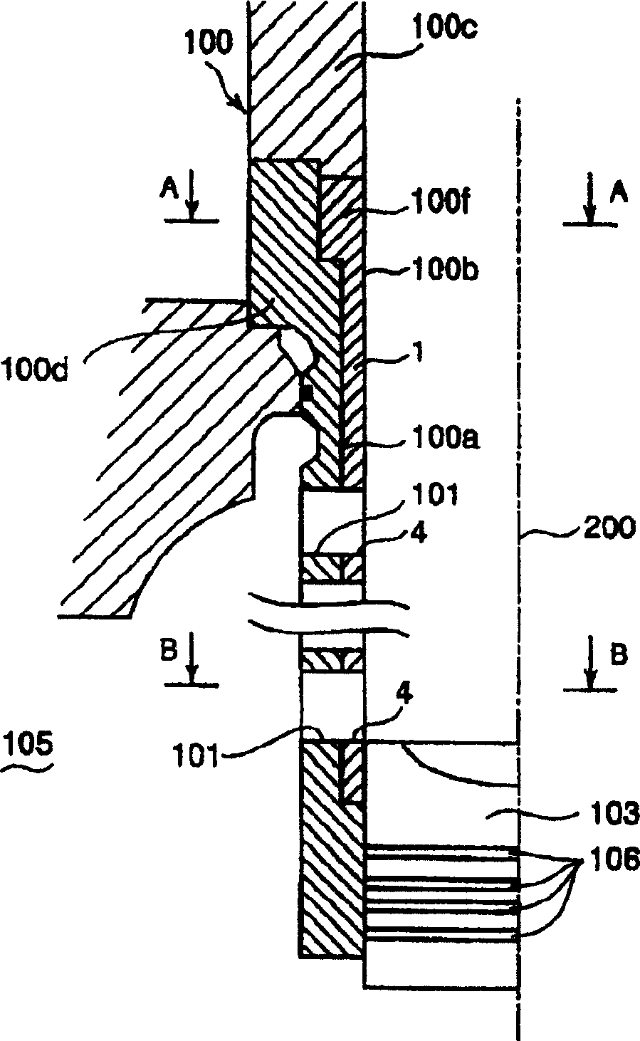
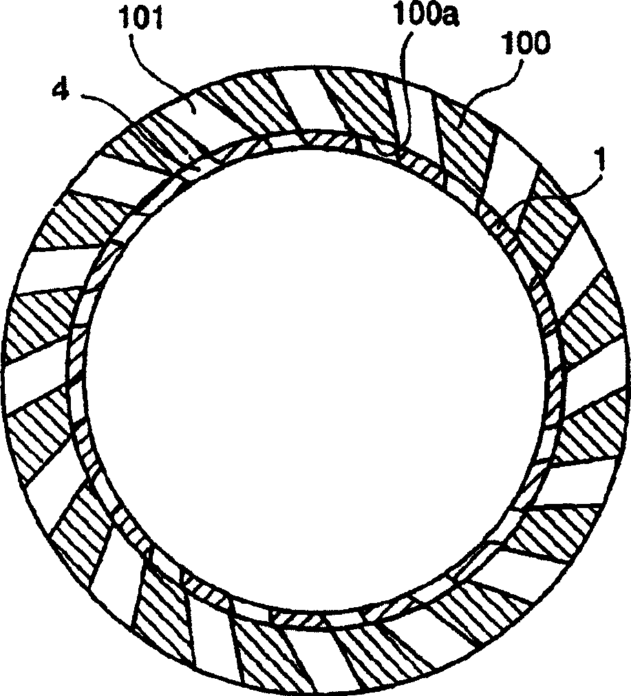
[0045] figure 1 It is a cross-sectional view of a large two-stroke engine along the cylinder centerline in the first to sixth embodiments of the present invention, wherein the air exchange port of the cylinder liner and the scavenging port of the scavenging control valve are shown, and figure 2 is along figure 1 Sectional view of midline B-B.

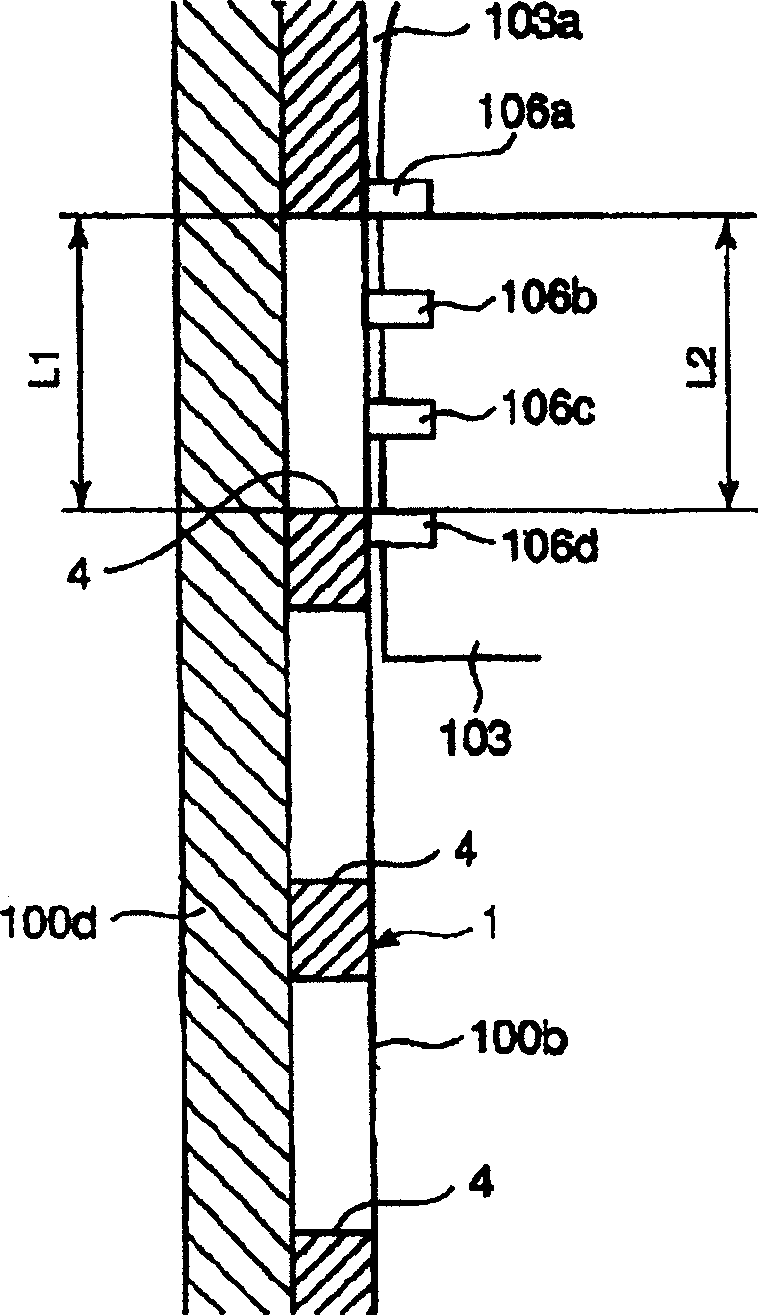
[0046] exist figure 1 and 2 Among them, reference numeral 100 is a cylinder liner composed of an upper sleeve portion 100c and an outer sleeve portion 100d, and 103 is a piston having a piston ring 106, which reciprocates in the upper sleeve portion 100c and the scavenging control...


PUM


Abstract

The invention aims to provide an internal combustion engine equipped with a scavenging control valve, in which blow-by of combustion gas from the upper annular space above the top piston ring to the scavenging ports is prevented by which reduction in engine performance due to deposition of combustion gas residuum to the scavenge openings and occurrence of piston ring sticking due to deposition of combustion gas residuum to the piston rings can be prevented, and further the amount of working oil to drive the scavenging control valve can be reduced resulting in decreased energy loss for pressurizing the working oil. An annular-shaped scavenging control valve is fitted-in to a fitting face formed on the inner side of the cylinder liner movably in circumferential direction of the cylinder liner for opening and closing said scavenging ports in order to allow scavenge air to be supplied into the cylinder or interrupted, said scavenging control valve has a plurality of scavenge openings arranged along circumferential direction and in a plurality of stages in axial direction thereof so that the scavenge openings are brought into communication or discommunication with the scavenging ports of the cylinder liner by moving the scavenging control valve in circumferential direction thereof, and the scavenge openings of each stage has a height L1 which is smaller than a inside distance L2 between a top piston ring and a bottom piston ring equipped to a piston of the engine as shown in.

Description

technical field [0001] The invention is applied to a large-scale two-stroke cycle engine, which has a plurality of air exchange ports arranged along the circumference of the cylinder liner at the lower part of the cylinder liner for introducing scavenging air into the cylinder, and the invention relates to a machine equipped with a scavenging air The internal combustion engine of the control valve device, the scavenging control valve device controls the opening and closing of the air exchange port so that when the scavenging control valve is rotated to the position where the scavenging air port of the scavenging control valve communicates with the air exchange port of the cylinder liner, the scavenging air is Provided to the cylinder, and when the scavenging control valve is rotated to the position where the scavenging port of the scavenging control valve closes the gas exchange port of the cylinder liner, the scavenging supply is interrupted. Background technique [0002] U...

Claims


Application Information

Patent Timeline
Patent Type & Authority Patents(China)
IPC IPC(8): F02B25/04F02B25/20F02F1/22F01L7/12
CPCF02B25/04F02B2075/025F02B25/20F02F1/22
Inventor 村田聪吉原定男吉川秀一柳润石田裕幸淀川胜男富屋靖夫
Owner MITSUBISHI HEAVY IND LTD
Why Eureka
Try Eureka