
LED chip and method for preparing the same

An LED chip and chip technology, applied in semiconductor devices, electrical components, circuits, etc., can solve the problems that the chip does not well solve the problems of light emitting efficiency and performance, complex bonding and separation processes, etc., to increase the luminous power of a single chip, The effect of increasing the light-emitting area and improving the light-emitting efficiency

Inactive Publication Date: 2009-06-24
HUAZHONG UNIV OF SCI & TECH
View PDF4 Cites 1 Cited by
  • Summary
  • Abstract
  • Description
  • Claims
  • Application Information

AI Technical Summary

Problems solved by technology

Before laser lift-off, GaN is bonded to Si or Cu, and GaN is separated from Si or Cu after lift-off. The bonding and separation processes are relatively complicated, and the structure of the final chip does not solve the problem of light emission. Efficiency and performance issues, especially LED chip luminous power and luminous area, need to be further improved

Method used


Image

  • LED chip and method for preparing the same
  • LED chip and method for preparing the same
  • LED chip and method for preparing the same

Examples


Embodiment Construction

[0034] Below in conjunction with accompanying drawing and example the present invention is described in further detail.

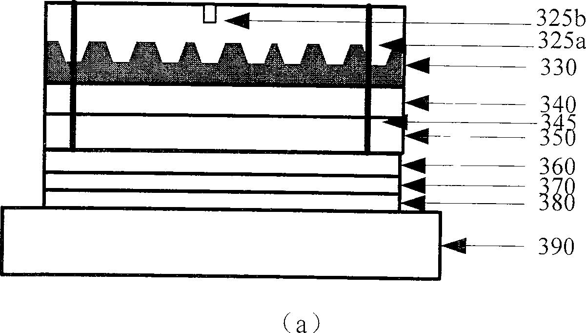
[0035] Such as image 3 As shown, the LED chip of the present invention is as follows from bottom to top: heat dissipation layer 390, bonding metal layer 380, insulating layer 370, P-type electrode 360, reflective layer 350, P-type GaN 340, N-type GaN 330 and N-type electrode, The upper surface of the N-type GaN layer 330 is a three-dimensional protrusion array, such as a conical or frustoconical structure, and the structure of the three-dimensional protrusions in the array will vary due to different process conditions. N-type electrode is made of ITO transparent electrode 325a and N electrode pad 325b, and the structure of the present invention also includes P electrode groove 345, and P electrode groove is after etching out 4 P electrode grooves at four corners of chip structure, from N The P-type GaN is etched onto the P-type GaN.

[0036] Such as Fi...


PUM


Abstract

The invention discloses an LED chip and a preparation method of the LED chip. The invention is characterized in that: a reflective layer, a P electrode and an insulation layer are deposited on a P-type GaN layer of an epitaxial piece layer by layer in sequence; a plurality of bonding metal materials are respectively deposited on the insulation layer and a heat-dissipation layer, and the two layers are bonded after being aligned; an underlay is thinned after the chip is reversed, and the underlay is stripped by laser focusing on the interface between the underlay of the epitaxial piece and a GaN buffer layer; the GaN buffer layer is etched until an N-type GaN appears, and then the exposed N-type GaN layer turns to be graphical, and a three-dimensional salient array is positioned on the upper surface of the N-type GaN layer; a layer of ITO is deposited on the graphical N-type GaN layer to be a translucent electrode, and the four angles of the structure are etched to form four groove structures from the top N-type GaN layer to an exposed P-type electrode layer; the ITO layer is etched to form an electrode hole, and metal is deposited on the ITO layer to make an N electrode welding spot. The invention has the advantages of increasing light extraction efficiency and the performance of the chip, reducing technological process, increasing single chip area and luminous area and improving light extraction power.

Description

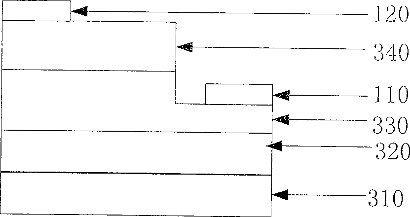
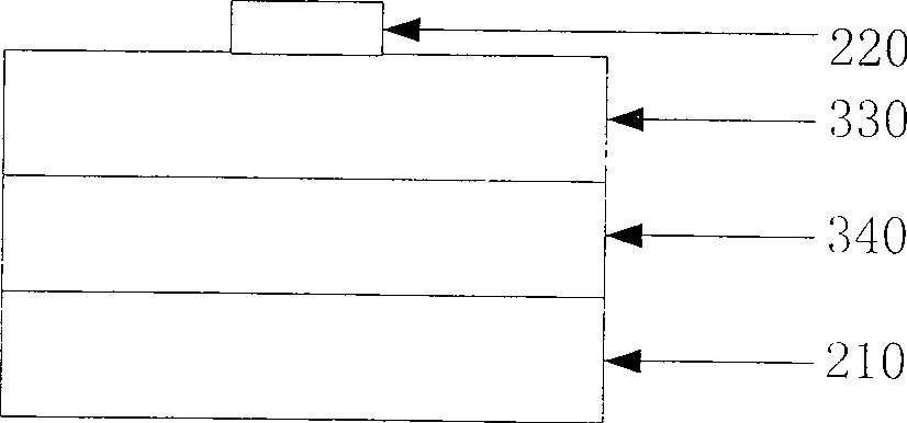
technical field [0001] The invention relates to the field of semiconductor optoelectronic devices, in particular to an LED chip and a preparation method thereof, and the LED chip is especially suitable for lighting. Background technique [0002] A light-emitting diode (LED) is a semiconductor light-emitting device with high electrical-to-optical conversion efficiency. At present, III-V compounds represented by gallium nitride (GaN) materials are important material systems for blue-green LEDs, and their wide application in many fields has promoted the rapid development of R&D and commercial devices. Now more commonly used LED chip structure such as figure 1 , figure 2 shown. figure 1 It is a schematic diagram of the structure of a commonly used front-mounted LED chip, and its basic structure includes: a substrate 310 , a GaN buffer layer 320 , N-type GaN 330 , P-type GaN 340 , and electrode pads 110 and 120 . figure 2 It is a structural schematic diagram of a flip-chip ...

Claims


Application Information

Patent Timeline
Patent Type & Authority Patents(China)
IPC IPC(8): H01L33/00H01L33/22H01L33/38
Inventor 周治平张斌吴廷伟
Owner HUAZHONG UNIV OF SCI & TECH
Learn More