
Synchronous trigger control method for transient light intensity test
A technology of synchronous triggering and control methods, applied in the field of optical testing, can solve problems such as incomplete waveforms, high false triggering rates, and loss of frontier data, and achieve the effects of complete test curves, less false triggering, and stable work
Patent Information
- Authority / Receiving Office
- CN · China
- Patent Type
- Patents(China)
- Current Assignee / Owner
- Publication Date
- 2009-08-19
Smart Images
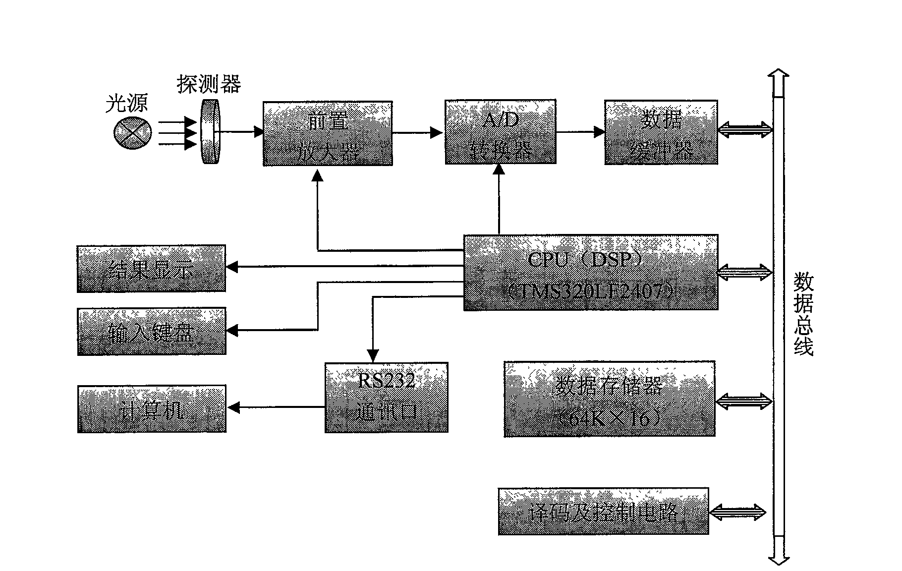
Figure 1 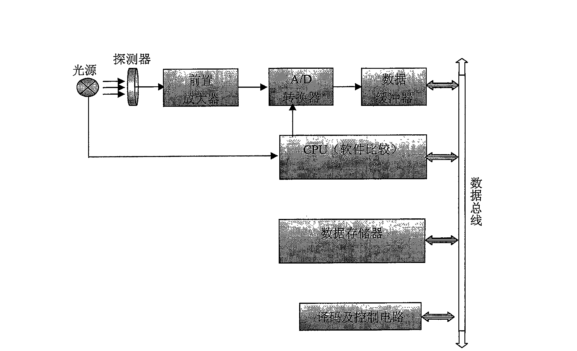
Figure 2 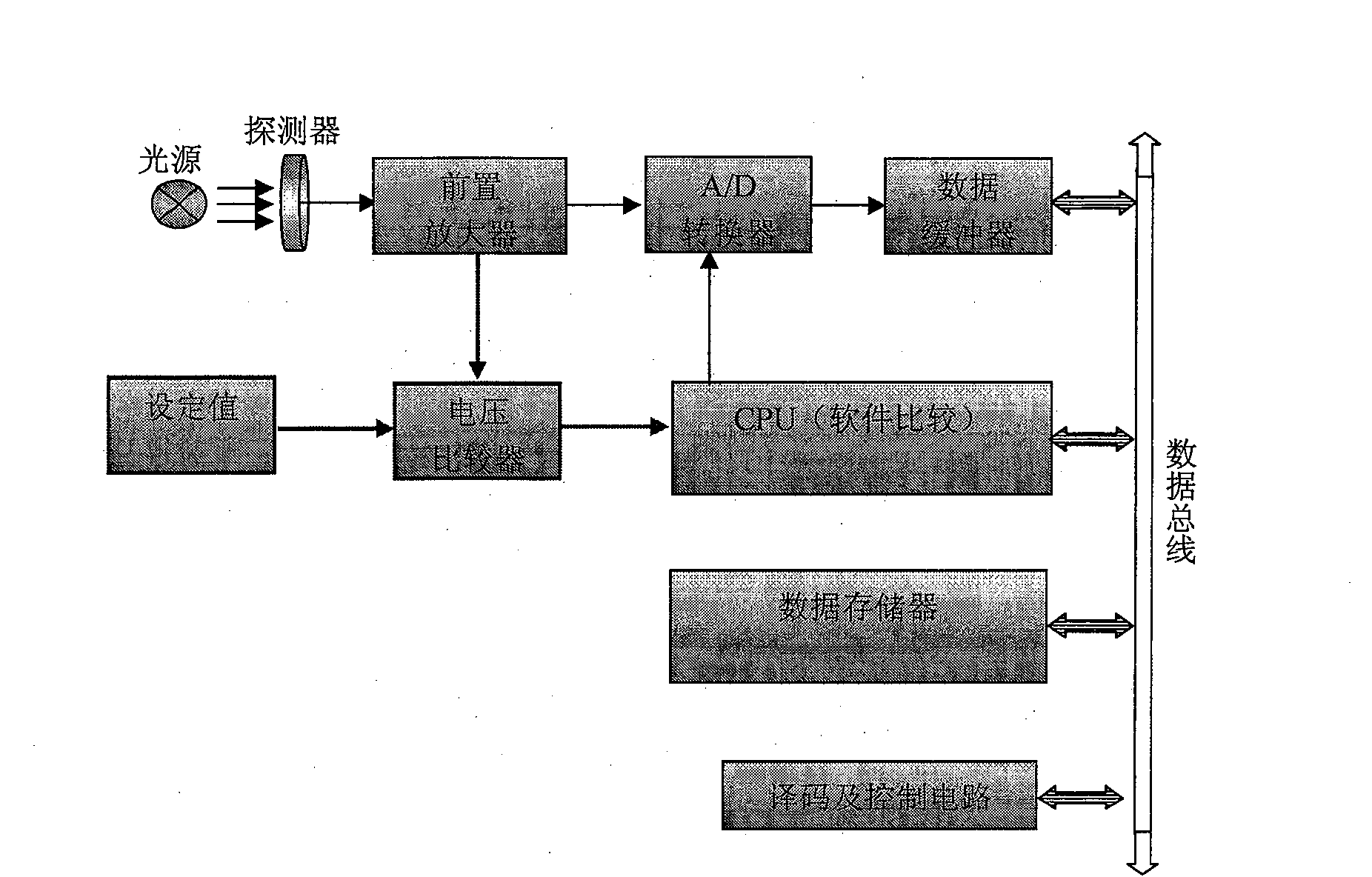
Figure 3
Abstract
Description
technical field
[0001] The invention belongs to the field of optical testing, and mainly relates to a light intensity testing method of a transient light source, in particular to a synchronous trigger control method during transient light intensity testing. Background technique
[0002] Due to the randomness of the transient light source, in order to accurately test the light intensity of the transient light source, it is necessary to know the starting point of the transient light source, so as to trigger the acquisition system to start the test, and obtain the entire flash process of the transient light source; its test principle such as figure 1 shown.
[0003] At present, there are two synchronous control methods used in the light intensity test of transient light sources, namely external synchronous trigger and light control trigger. External sync trigger (see figure 2 ) The principle of the test circuit is to output a lighting synchronous signal to the central proce...
Examples
Embodiment Construction
[0013] The present invention will be further described in detail below in conjunction with the accompanying drawings and preferred embodiments.
[0014] The preferred embodiment of the present invention is used for the synchronous control and testing of the transient light intensity tester. In order to ensure the accurate measurement of the transient signal, a synchronous control and data acquisition circuit is designed. The circuit principle is as follows: figure 1 and Figure 4 shown. The system is composed of preamplifier, AD converter, central processing unit CPU, data memory, decoding and control circuit; among them, the preamplifier converts the photocurrent signal output by the receiver into a voltage signal and performs signal amplification. The signal is input to the A / D converter and converted into a digital quantity. The quantized value is read by the central processing unit CPU, judged and processed and stored in the data memory. The decoding and control circuit r...