Supercharge Your Innovation With Domain-Expert AI Agents!

Tamping forming apparatus

A molding device and tamping hammer technology, applied to ceramic molding machines, manufacturing tools, etc., can solve problems such as difficulty in improving product quality and production efficiency, unsuitable for large-diameter container production, and difficulty in improving internal quality, so as to overcome product faults , beautiful appearance, reliable quality

Inactive Publication Date: 2009-09-02
BASAN SPECIAL FIRE RETARDANT MATERIAL FACTORY SHANDONG
View PDF4 Cites 0 Cited by
  • Summary
  • Abstract
  • Description
  • Claims
  • Application Information

AI Technical Summary

Problems solved by technology

At present, the molding method is only limited to manual hand-held tamping hammer operation or is suitable for the production of small-caliber heat-resistant pipes; after retrieval 03200204.1 "Refractory Material Molding Device" is horizontal, with machine feeding components, plastic components, and negative pressure molding Composed of components and driving components, it is suitable for the production of small-diameter high-temperature-resistant tubes, but not suitable for the production of large-diameter container cylinders
The factory mainly produces large-diameter container cylinders, which were improved by air hammer ramming after testing, but due to the large production batches, it is difficult to improve product quality and production efficiency; later improved to hydraulic molding, and due to step-by-step feeding, the product appeared delamination phenomenon , the internal quality is difficult to improve, the appearance is unsatisfactory, and it employs many people and consumes a lot of energy

Method used


Image

  • Tamping forming apparatus
  • Tamping forming apparatus
  • Tamping forming apparatus

Examples


Embodiment Construction

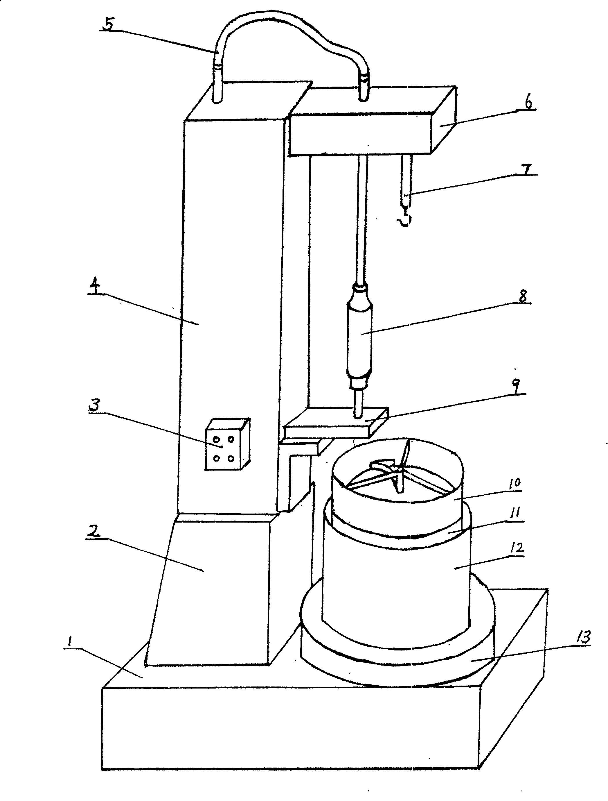
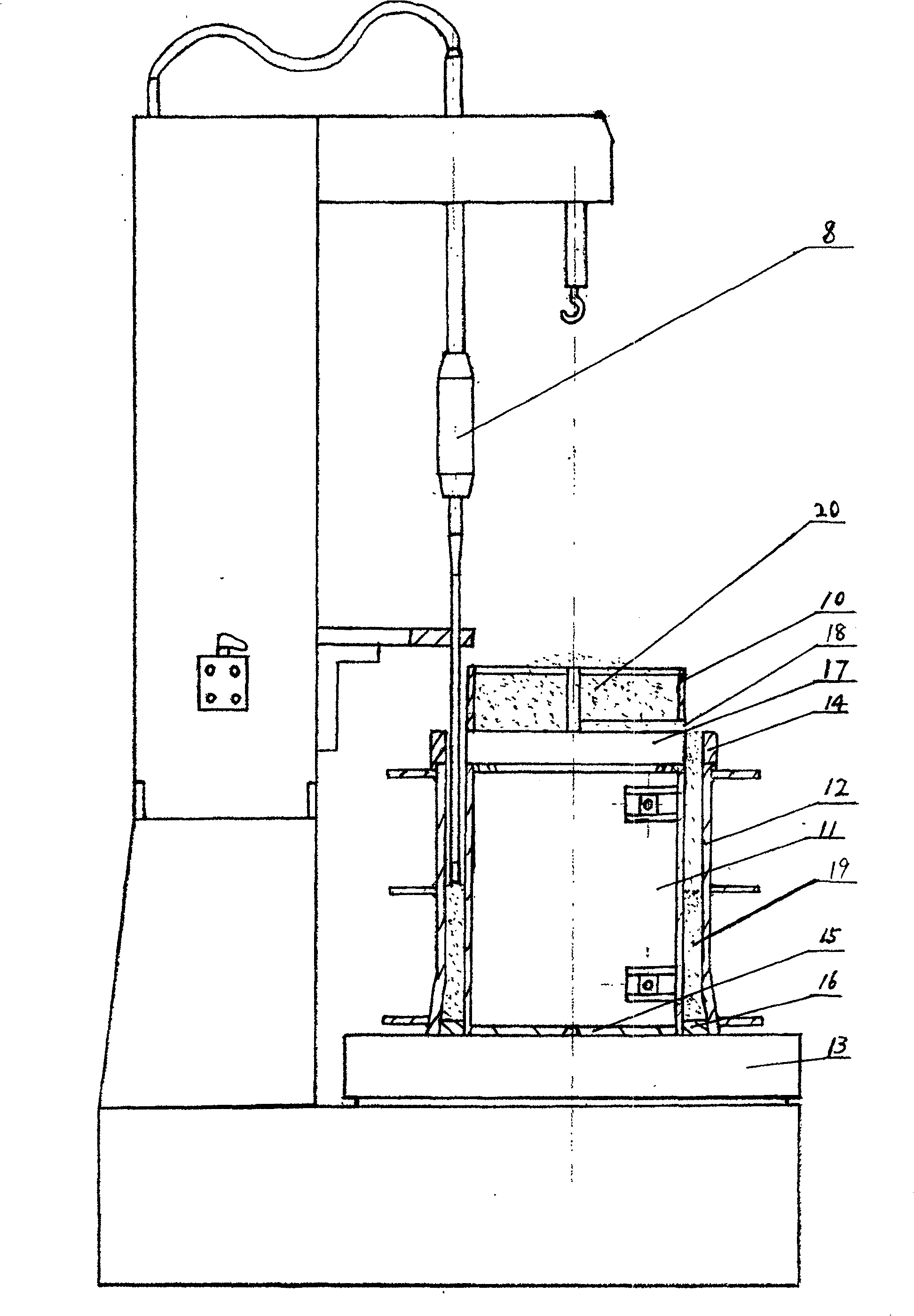
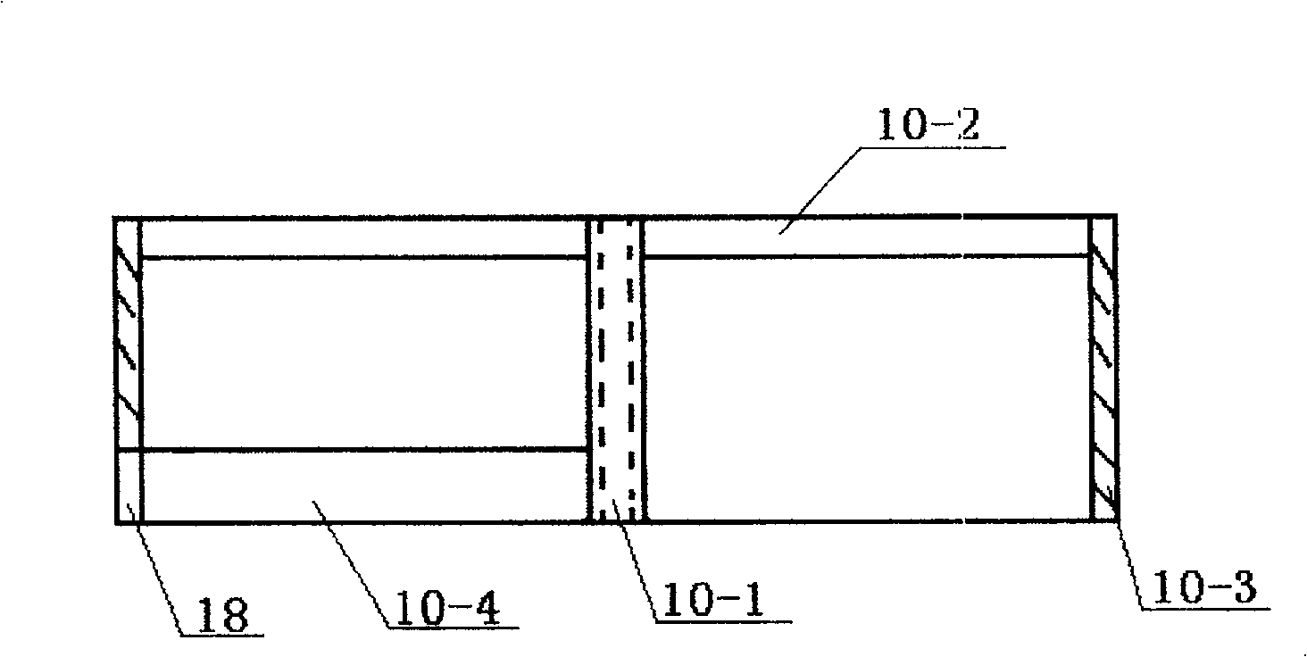
[0019] figure 1 , 2 As shown, the present invention includes a base 1, a power box 2, an electric control system 3, a column 4, a hose 5, a beam 6, a mold core lifting mechanism 7, a tamping hammer 8, a slide 9, a distributor 10, and an elastic mold core 11. Mould sleeve 12, rotating worktable 13; chassis 15 is bolted to the rotating worktable 13 as a part of the worktable; the electric control system 3 is located on the column 4 and electrically connected to the electrical components in the column 4; base 1, The power box 2, the column 4, the beam 6, the mold core lifting mechanism 7, the sliding slide 9, the rotating table 13, and the chassis 15 are connected as a whole as a whole supporting system.

[0020] The lower end of the tamping hammer 8 passes through a slide 9 with one end fixed on the column 4, corresponding to the product 19, and the upper end of the tamping hammer 8 passes through a beam 6 fixed at the upper end of the column 4 at one end and communicates with the...


PUM


Abstract

The tamping forming device of the present invention is composed of a support frame and a ramming device, and is characterized in that: it is also provided with a distributor, a flat mouthpiece, a mold and a turner; the distributor is positioned above the mold core above the rotary table, and the distributor With the positioning sleeve as the center and the shell as the frame, at least 2 supporting frames are fixedly connected in the middle to form a frame-shaped distributor. The inner end of the involute baffle is fixedly connected with the positioning sleeve, and the outer end of the involute baffle is connected to the shell outlet connection. It has many advantages: First, the production process is automated, the cloth and tamping are carried out continuously during production, and the whole process of product production can be completed at one start, which overcomes the phenomenon of product faults, and the production efficiency, product quality and working conditions are superior to other equipment and methods; Second, the product has beautiful appearance and reliable quality: the product is smooth and beautiful, with uniform density; the product density reaches 2.7Kg / Cm2. The third is to improve efficiency and improve the working environment: taking the production of SiC tubes as an example, 2 people operate, 12 pieces per shift, and the labor intensity is low, which is 3 times higher than that of hydraulic press production; Fourth, it saves a lot of energy compared with hydraulic production.

Description

Technical field: [0001] The tamping molding machine of the present invention is mainly used for tamping molding of pipe-type refractory products, and belongs to the field of refractory material molding equipment. Background technique: [0002] Tamping molding in the refractory industry is an ancient molding method. At present, the molding method is limited to manual hand-held tamping hammer operation or suitable for the production of small-caliber heat-resistant pipes; after retrieval, 03200204.1 "Refractory Material Molding Device" is a horizontal type, and the machine feeds components, plastic components, and negative pressure molding. The components and drive components are suitable for the production of small-diameter high-temperature resistant pipes, but not for the production of large-diameter container tubes. The factory mainly produces large-caliber container barrels, which have been tested and improved to use air hammer ramming. However, due to the large production batch...

Claims


Application Information

Patent Timeline
Patent Type & Authority Patents(China)
IPC IPC(8): B28B3/02
Inventor 李应征 任庆祥 张允刚李应征任庆祥张允刚
Owner BASAN SPECIAL FIRE RETARDANT MATERIAL FACTORY SHANDONG
Features
  • R&D
  • Intellectual Property
  • Life Sciences
  • Materials
  • Tech Scout
  • Unparalleled Data Quality
  • Higher Quality Content
  • 60% Fewer Hallucinations
Learn More