Manufacture method of pole of super capacitor

A technology for supercapacitors and manufacturing methods, applied in capacitors, electrolytic capacitors, electrochemical generators, etc., can solve the problems of activated carbon falling off and the inability to adjust the active material of single-chip electrodes, etc., achieve small leakage current, long life, and increase specific energy and the effect of the self-discharge rate

A technology for supercapacitors and manufacturing methods, applied in capacitors, electrolytic capacitors, electrochemical generators, etc., can solve the problems of activated carbon falling off and the inability to adjust the active material of single-chip electrodes, etc., achieve small leakage current, long life, and increase specific energy and the effect of the self-discharge rate

CN100550237CInactive Publication Date: 2009-10-14SHANGHAI AOWEI TECH DEV

Image

  • Manufacture method of pole of super capacitor
  • Manufacture method of pole of super capacitor
  • Manufacture method of pole of super capacitor

Examples


Embodiment Construction

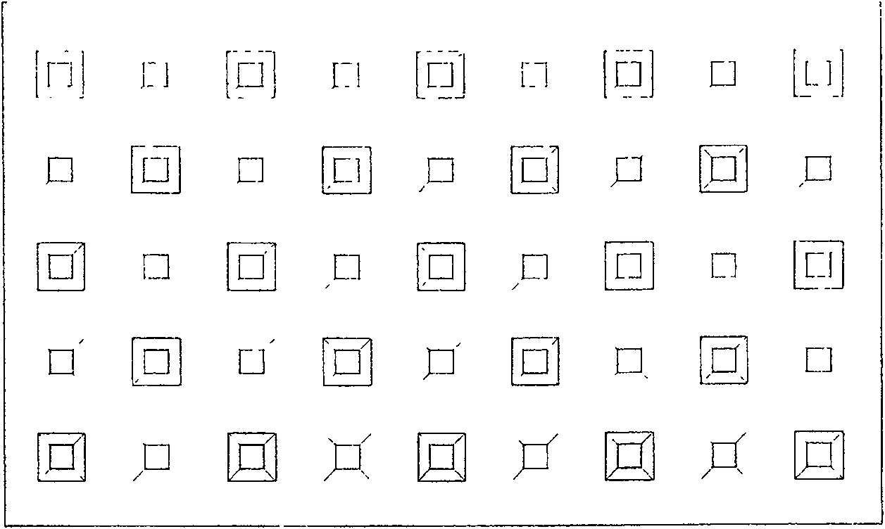
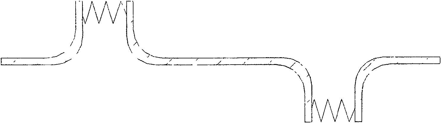
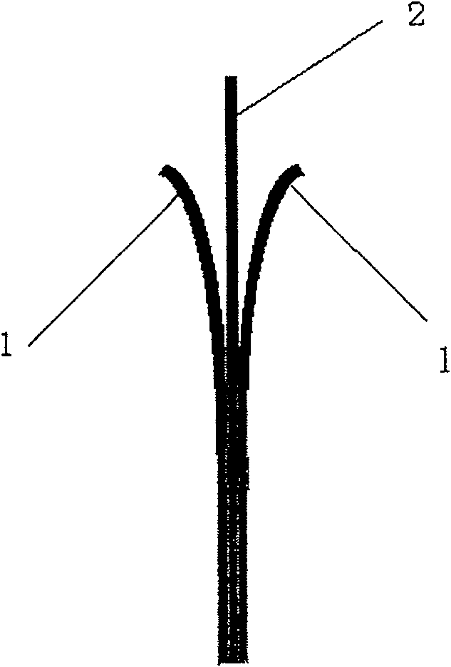
[0015] Cut the metal foil strip with a thickness of 0.05-0.2mm and a burr hole or square hole on the surface with a spacing of 0.5-2.0mm to the required size; mix activated carbon and PTFE emulsion in a ratio of 10:0.5-10:1, mix Use a stirring rod to stir in the same direction until the glue is connected, and then put it on the rolling machine to extend the horizontal and vertical alternate rolling until the carbon sheet has a certain elasticity and toughness, and the carbon sheet is made into a flexible activated carbon of 0.2-2.0mm sheet 1; the flexible activated carbon sheet 1 is attached to the burr metal belt current collector 2 with a press or a roller machine to make a supercapacitor electrode, as attached image 3 shown. The diameter of the burr round hole is 0.5~2.0mm, and the size of the square hole is (0.5×0.5mm)~(2.0×2.0mm). Metal foil strips refer to nickel metal foil strips, copper metal foil strips, and nickel-plated steel strips. The burrs on the metal foil ta...


PUM

PropertyMeasurementUnit
diameteraaaaaaaaaa

Abstract

This invention discloses a burr metal strip collector and its usage in a super capacitor, in which, a flexible active carbon plate is adhered on said burr metal foil with the thickness of 0.05~0.2mm and burr round hole or square hole in the gap of 0.5~2.0mm by vertical pressing or rolling to process an electrode of a super capacitor to increase the loading volume of the active carbon and alter the surface state of a collector.

Description

technical field [0001] The invention relates to a method for manufacturing a supercapacitor electrode. Background technique [0002] Supercapacitor is a new type of energy storage device developed in recent years. With the needs of electric vehicles and high-power systems, supercapacitors have been paid more and more attention by people. Hybrid supercapacitors are widely used in electric buses because of their high specific energy and high power. Vehicles, heavy machinery energy compensation and other aspects can play an important role. [0003] At present, the manufacturing methods used to manufacture supercapacitor electrodes are mainly coating method and foamed metal pulping method. The disadvantage of the coating method is that there is little room for adjustment of the amount of carbon on the activated carbon. Too thick a carbon layer will cause the activated carbon layer to fall off. Thus affecting the performance; the method of foaming metal pulp can increase the amo...

Claims


Application Information

Patent Timeline
14 Oct 2009
Publication
CN100550237C
IPC
H01G9/00; H01M4/64; H01M10/00; H01M14/00
CPC
Y02E60/13; Y02E60/10
Inventors
王国庆; 王然