Roboticized intelligent fixture system

A robot and tooling technology, applied in the field of manufacturing engineering, can solve the problems that combined tooling is difficult to meet the high-efficiency and high-precision machining, design, manufacturing, driving, and control of aircraft thin-walled curved surface parts, and it is difficult to meet the actual needs of aerospace vehicles. Achieve the effects of simplified daily maintenance, strong scalability, and reduced application costs

Inactive Publication Date: 2009-10-21
TSINGHUA UNIV
View PDF4 Cites 4 Cited by
  • Summary
  • Abstract
  • Description
  • Claims
  • Application Information

AI Technical Summary

Problems solved by technology

[0005] Although the existing combined tooling can obtain the corresponding tooling positioning / supporting surface through manual adjustment according to the design and process requirements of the skin surface contour, which has certain flexibility, but this kind of tooling requires manual operation, which not only is cumbersome to debug, but also has poor precision and low efficiency. Low, labor-intensive, and requires high technical level of staff
These defects make it difficult for combined tooling to meet the requirements of high-efficiency and high-finish machining of aircraft thin-walled curved parts
[0006] On the other hand, although an automated flexible tooling can be formed through an all-electric point-by-point drive scheme, due to the large number of positioning and supports (tens to hundreds) required for the machining of aircraft thin-walled curved parts, it is necessary to carry out There will be more than hundreds of driving and control links, which makes the realization of flexible tooling according to the all-electric drive scheme will make the structure of the entire tooling system too complicated, not only difficult to design, manufacture, drive, and control, but also too expensive to Meet the actual needs of aerospace vehicle manufacturing enterprises
In addition, this solution also has a large volume of positioning and supporting links, and it is difficult to ensure that more positioning and supporting points are arranged within the effective range to increase the support density and support stiffness of thin-walled curved workpieces, thereby reducing workpiece deformation and improving processing. Accuracy and other issues

Method used


Image

  • Roboticized intelligent fixture system
  • Roboticized intelligent fixture system
  • Roboticized intelligent fixture system

Examples


Embodiment Construction

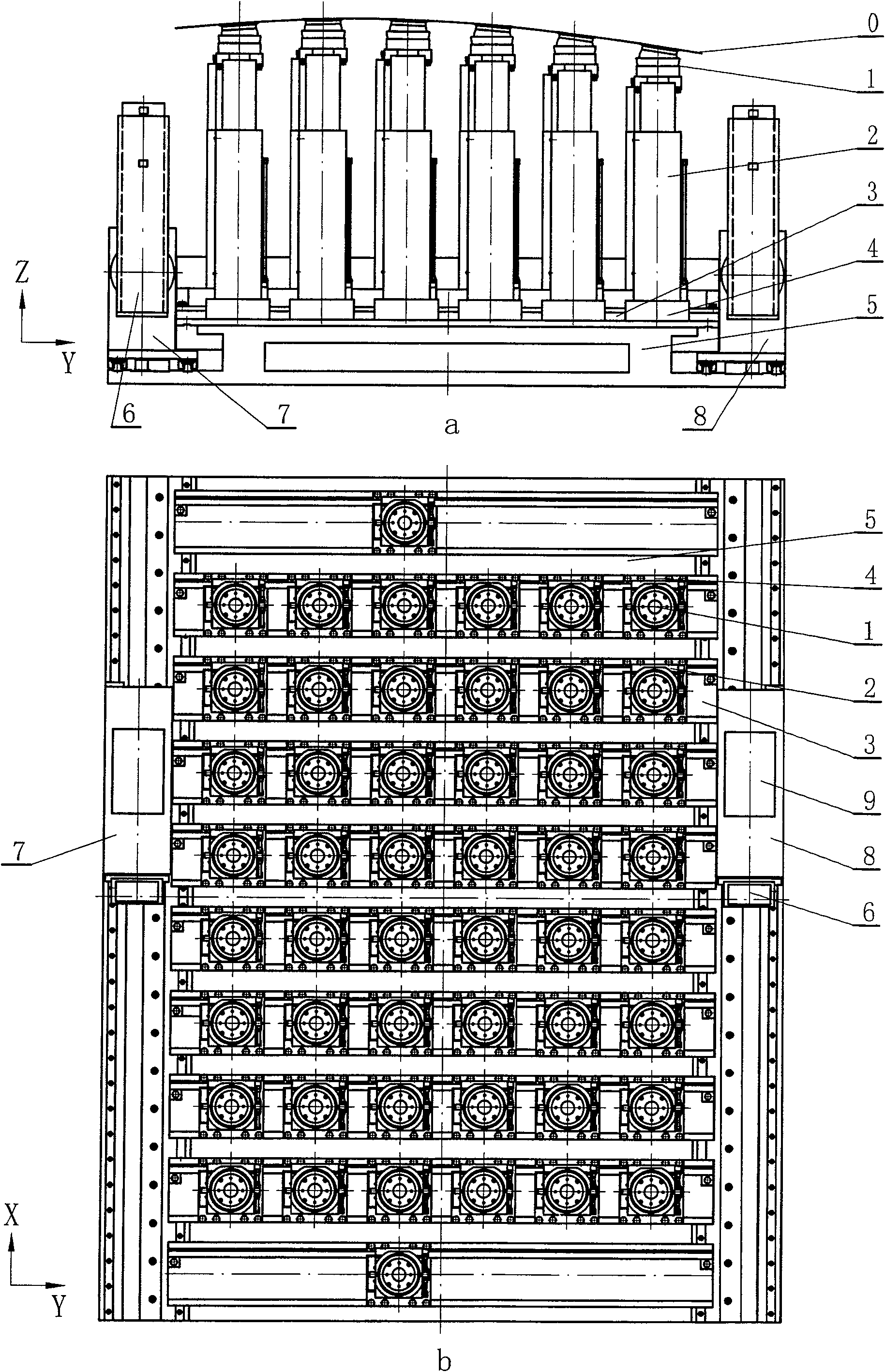
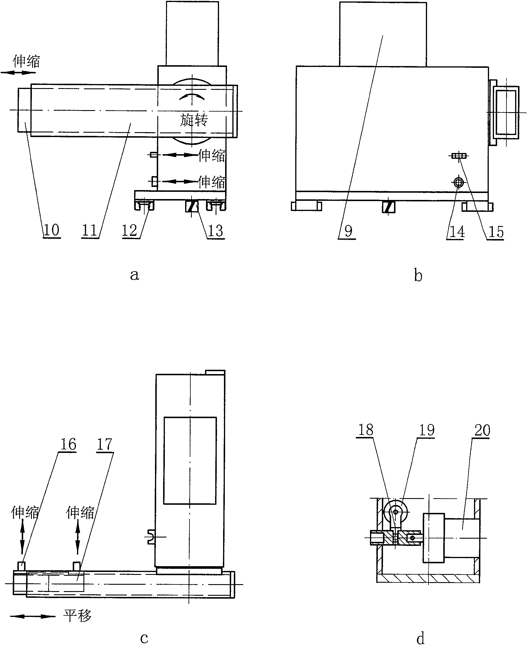
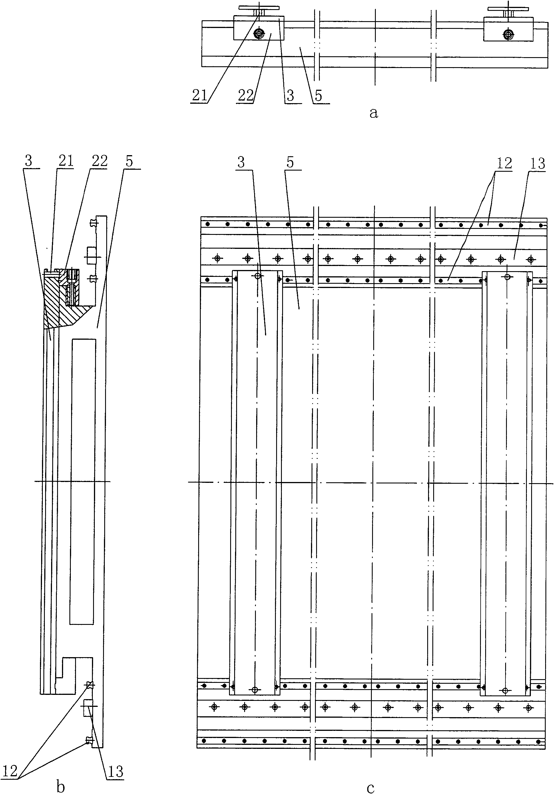
[0031] In order to achieve the above purpose, the invention figure 1 The robotized intelligent tooling system (hereinafter referred to as the tooling system) is shown. The system controls the coordinated movement of the dual robots through a computer to realize the intelligent operation of the tooling system. The whole system includes a base part 5, a moving beam part 3, a saddle part 4, a telescopic unit 2, a universal vacuum suction head 1, a left robot 7, a right robot 8, a control computer 9 and other components. It is characterized in that: the base part 5 is equipped with a plurality of moving beam parts 3, and each moving beam part moves along the X coordinate; the moving beam part is equipped with a plurality of sliding saddle parts 4, and each sliding saddle part moves along the Y coordinate; A telescopic unit 2 is installed on the saddle part, and the telescopic unit drives the universal vacuum suction head 1 at its top to move along the Z coordinate. Wherein, the ...


PUM


Abstract

The invention relates to a roboticized intelligent manufacture-equipment system, which is used for the processing field of airborne craft thin-wall curved parts. The roboticized intelligent manufacture-equipment system is characterized in that the whole system comprises a base component, a dynamic beam component, a saddle component, a telescopic unit, a universal vacuum sucker, a left robot and a right robot, as well as a control computer. Under the control of the computer, after realizing the accurate abutting joint on the dynamic beam component through a docking mechanism, the robots do the synchronized motion together for adjusting to a certain position in the X direction, and the dynamic beam component realizes that the base component is locked through a retaining mechanism; at the same time, after the large arm of the robot main machine hand is rotated to the horizontal position, small arms extend out in turn, the palm moves, and then the fingers extend to grasp the telescopic unit fixed on the saddle component, so as to ensure that the telescopic unit moves in the Y direction for adjusting to a certain position; later, the telescopic unit moves in the Z direction for adjusting; in the end, through the universal vacuum sucker fixed on a telescopic mast, the curved face shape used for supporting the thin-wall curved parts is formed. The roboticized intelligent manufacture-equipment system is used for processing various parts, thereby greatly improving the flexibility of the production.

Description

Technical field: [0001] The invention relates to a robotized intelligent tooling system for processing aircraft thin-walled curved surface parts, belongs to the technical field of manufacturing engineering, and specifically relates to the flexible process equipment technology for aircraft skin manufacturing. Background technique: [0002] A major problem in aviation and aerospace manufacturing is: when the large skin of an aircraft adopts the "forming first and then processing" process, the semi-finished product after forming is an elastic thin-walled part with extremely poor stiffness and its surface contour is a free-form surface. The six-point positioning principle and corresponding process equipment technology can no longer be applied to the efficient and high-precision machining of such parts, which seriously affects the quality and efficiency of product assembly. Facing this problem, it is necessary to further study new surface positioning methods for elastic bodies an...

Claims


Application Information

Patent Timeline
Patent Type & Authority Patents(China)
IPC IPC(8): B23Q3/00B25J9/00
Inventor 周凯钱琪门延武
Owner TSINGHUA UNIV
Why Eureka
Try Eureka