
Coupled apparatus used between heat phonomotor and refrigerating device driven by the same

A technology of thermoacoustic engine and coupling device, which is applied in the direction of hot gas variable volume engine device, refrigerator, machine/engine, etc., can solve the problems of low efficiency, consumption of helium, and poor refrigeration performance.

Inactive Publication Date: 2009-12-02
TECHNICAL INST OF PHYSICS & CHEMISTRY - CHINESE ACAD OF SCI
View PDF6 Cites 0 Cited by
  • Summary
  • Abstract
  • Description
  • Claims
  • Application Information

AI Technical Summary

Problems solved by technology

First, pulse tube refrigerators and thermoacoustic refrigerators usually use gases such as helium as the working medium, and it is advisable to work at a relatively low frequency. When the operating frequency increases, its refrigeration performance usually deteriorates
When the thermoacoustic engine uses helium as the working medium, if it is to make it work at a frequency below 50Hz, the length of the resonance tube must reach more than 8m. Such a huge volume is of course not conducive to practical application, and it will also consume a lot of The cost of helium is also very high
Second, due to the large size of the thermoacoustic engine, if the refrigerator and the engine are directly coupled, the pressure amplitude in the refrigerator cannot be higher than the pressure amplitude in the engine, so the engine will consume most of the energy due to viscous dissipation. Part of the sound work, only a small amount of sound work enters the refrigerator, so the efficiency is very low

Method used


Image

  • Coupled apparatus used between heat phonomotor and refrigerating device driven by the same
  • Coupled apparatus used between heat phonomotor and refrigerating device driven by the same
  • Coupled apparatus used between heat phonomotor and refrigerating device driven by the same

Examples


Embodiment 1

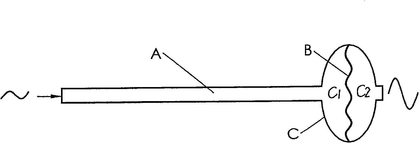
[0053] Embodiment 1: adopt Figure 5 The coupling device shown; the coupling device includes: a cavity C;

[0054] An elastic diaphragm B installed in the cavity C, the elastic diaphragm B divides the cavity C into a first chamber C1 and a second chamber C2;

[0055] A long tube A connected to the side wall of the cavity C and communicated with the first chamber C1;

[0056] A short tube F communicating with the other side wall of the cavity C and communicating with the second chamber C2;

[0057] The other end of the long pipe A is communicated with the feedback pipe 12 of the thermoacoustic engine through the ball valve 1;

[0058] The other end of the short pipe F communicates with the water cooler 21 of the refrigerator.

[0059] The engine is a traveling wave thermoacoustic engine (marked with D), and the traveling wave thermoacoustic engine is composed of the first water cooler 2 of the engine, the regenerator 3 of the engine, the heater 4 of the engine, the heat buffer...

Embodiment 2

[0061] Embodiment 2: adopt Figure 6 The structural device shown. The size of the engine D is the same as that of the engine in Embodiment 1; the length of the long pipe A in the coupling device is 1.6m, and the diameter is 17mm, and it communicates with the engine at the junction of the annular ring formed by the various parts of the engine and the resonant tube 13; the cavity The structure and size of C are the same as the cavity in Example 1. The area of ​​the elastic film B in the cavity C perpendicular to the flow direction of the working medium is about 50 times that of the cross section of the long tube A; the refrigerator is U-shaped. Two-stage pulse tube refrigerator; the primary regenerator 31 of the refrigerator is 80 mm long and 30 mm in diameter; the secondary regenerator 32 of the refrigerator is 80 mm long and 12 mm in diameter; the primary pulse tube 10 of the refrigerator is 104 mm long and 12 mm in diameter; The secondary pulse tube 101 is 160 mm long and 8 ...

Embodiment 3

[0062] Embodiment 3: adopt Figure 7 The structural device shown. The engine is a standing wave thermoacoustic refrigerator. The total length of the thermal cavity, heater, regenerator and water cooler is 238mm, and the diameter is 100mm. The resonance tube consists of a tapered tube with a length of 3m and a diameter ranging from 100mm to 200mm, and a straight tube with a diameter of 200mm at one end and a length of 0.5m. The long pipe A in the coupling device has a length of 1m and a diameter of 50mm, and communicates with the engine through a ball valve. The elastic diaphragm is a 1 mm thick nitrile rubber film.

[0063] The diameter of the elastic membrane B in the cavity C is 120 mm, and its area perpendicular to the flow direction of the working medium is about 5 times that of the long tube A, and the total height of the cavity C is 100 mm. The refrigerator is a thermoacoustic refrigerator, the total circumference of the annular ring is 1.2m, the diameter of the feedb...


PUM


Abstract

The invention relates to a coupling device for a thermoacoustic engine and a refrigerator driven by it, comprising: a cavity; an elastic diaphragm installed in the cavity, and the elastic diaphragm divides the cavity into first chambers and the second chamber; a long tube communicated on one side wall of the cavity and communicated with the first chamber; a short tube communicated on the other side wall of the cavity and communicated with the second chamber; The other end is connected to the feedback tube of the thermoacoustic engine; the other end of the short tube is connected to the water cooler of the refrigerator; the coupling device can amplify the pressure amplitude of the pressure wave generated by the thermoacoustic engine after passing through the long tube and the cavity, Thereby, the utilization rate of the sound power of the system by the refrigerator is improved; the elastic diaphragm sandwiched in the middle of the cavity isolates the working gas in the engine and the refrigerator, so that the engine can use nitrogen and other gases as the working fluid to reduce the system frequency, and the refrigerator can use helium. Gas and other gases are used as working fluids to maintain their good refrigeration performance.

Description

field of invention [0001] The present invention mainly relates to the field of energy utilization and refrigeration, in particular to a coupling device used between a thermoacoustic engine and a refrigerator driven by it; the coupling device can improve the utilization rate of sound power of the refrigerator system driven by a thermoacoustic engine, Reduce operating frequency. Background technique [0002] The thermoacoustic engine-driven pulse tube refrigerator, or thermoacoustic refrigerator, is a new type of refrigeration technology that has no moving parts at all. It uses thermal energy as power, through the oscillation of gas, converts internal energy into sound work in the engine, and consumes sound work in the refrigerator to produce cooling effect. It is environmentally friendly, safe, and has a long service life, so it has a very good application prospect. [0003] At present, its refrigeration temperature range has covered from room temperature to liquid hydrogen ...

Claims


Application Information

Patent Timeline
Patent Type & Authority Patents(China)
IPC IPC(8): F25B9/14F25B9/00F02G1/00
CPCF25B2309/1403F25B9/145F25B2309/1402
Inventor 罗二仓胡剑英戴巍吴张华
Owner TECHNICAL INST OF PHYSICS & CHEMISTRY - CHINESE ACAD OF SCI
Learn More