

Spray technology of high voltage insulator surface coating and its spray device
A technology for high-voltage insulators and surface coating, which is applied to devices for coating liquid on surfaces, spray devices, coatings, etc., to achieve the effects of promoting popularization and application, making good use of space, and reducing costs
- Summary
- Abstract
- Description
- Claims
- Application Information
AI Technical Summary
Problems solved by technology
Method used
Image

Examples
Embodiment 1
[0025] Example 1: Film coating on the surface of XWP-70 high voltage porcelain insulator
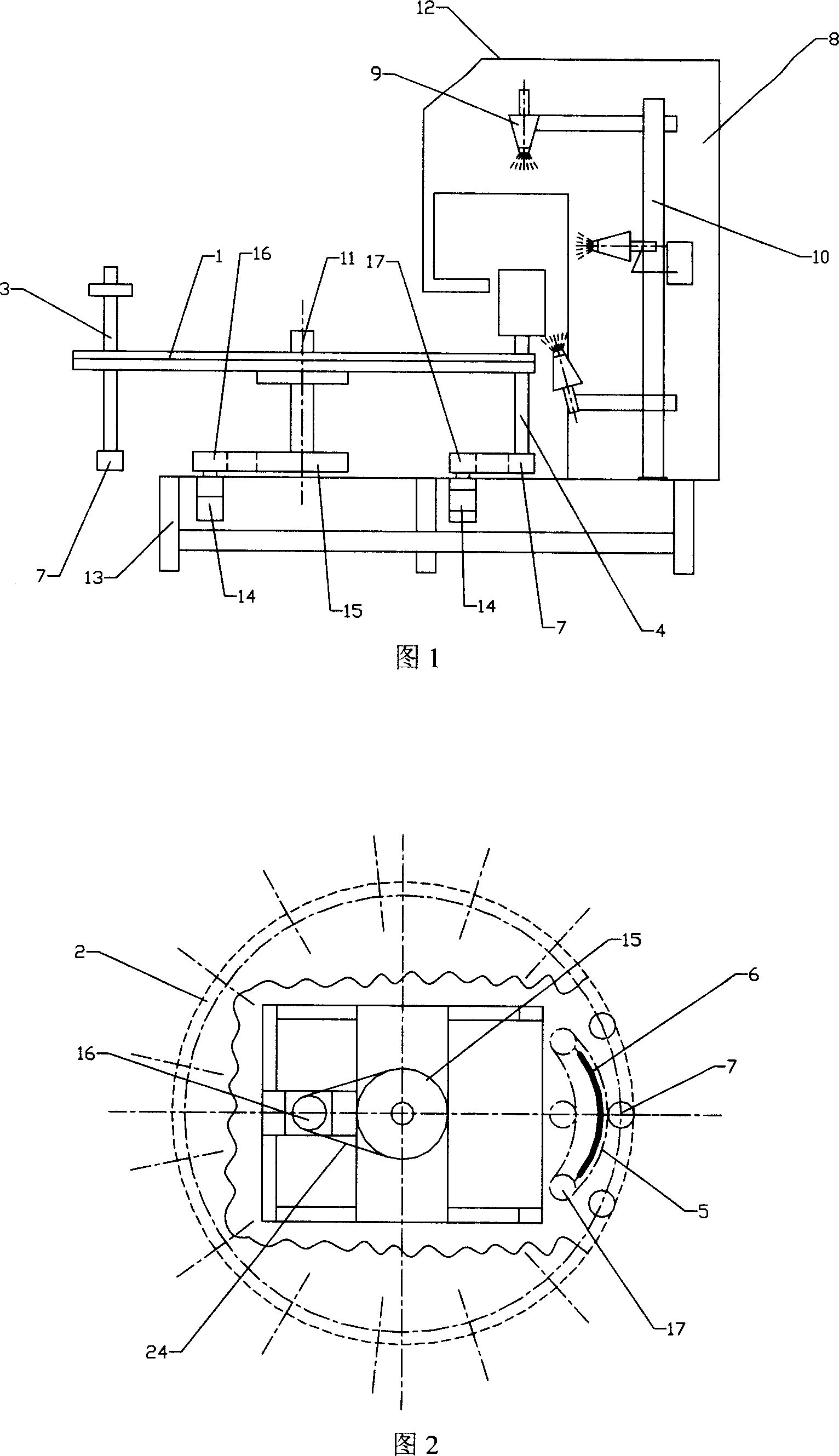
[0026] After cleaning and drying the surface of the poured and molded commercial XWP-70 porcelain insulator, put it into the insulator bracket on the working disc, control the rotation (revolution) speed of the working disc to 1r / min, and the insulator's rotation speed to 90r / min, the flow rate of the three spray guns is: the flow rate of the upper spray gun is 4mL / min, the flow rate of the middle spray gun is 5mL / min, the flow rate of the lower spray gun is 4mL / min, the air pressure of the three spray guns is: the air pressure of the upper spray gun is 0.08MPa, and the air pressure of the middle spray gun is 0.1 MPa, the air pressure of the lower spray gun is 0.08MPa, and the solid content of titanium dioxide in the spraying liquid is 3.0wt%. After the sample passes through the spraying chamber (the effective spraying time is about 15s), an insulator coated with a titanium dioxide film i...
Embodiment 2
[0028] Example 2: Film coating on the surface of XP-70 high voltage porcelain insulator
[0029]After cleaning and drying the surface of the poured XWP-70 high-voltage porcelain insulator (this insulator has no middle shed, only the upper and lower sides), put it into the insulator bracket with the working disc, open the upper and lower two spray gun. Control the rotation speed of the working disc to 0.3r / min, the rotation speed of the insulator to 90r / min, the flow rate of the spray gun is: the flow rate of the upper spray gun is 4mL / min, the flow rate of the lower spray gun is 5mL / min, the air pressure of the spray gun is: the flow rate of the upper spray gun The air pressure is 0.08MPa, the air pressure of the lower spray gun is 0.08MPa, the solid content of titanium dioxide in the spraying liquid is 3.0wt%, and the sample is taken out after passing through the spraying chamber (the effective spraying time is about 15s), and an insulator coated with a titanium dioxide film ...
PUM
 Abstract
Description
Claims
Application Information