
Rotating piston engine with compressing working independent chamber

A rotary engine, annular cavity technology, applied in the direction of internal combustion piston engine, combustion engine, machine/engine, etc., can solve the problems of complex engine mechanism, reduced weight and size of the whole machine, and reduced charging efficiency.

Inactive Publication Date: 2007-07-18
陈崟
View PDF0 Cites 5 Cited by
  • Summary
  • Abstract
  • Description
  • Claims
  • Application Information

AI Technical Summary

Problems solved by technology

The improvement of engine speed and power is greatly restricted, and the efficiency of the power transmission mechanism can only reach a certain level
[0005] 2. The crank-link mechanism of the reciprocating engine makes it difficult to reduce the weight of the whole machine and further reduce the overall size
[0006] 3. The existence of the valve and its driving cam mechanism not only increases the weight and parts of the engine, but also increases the noise of the engine
[0007] 4. During the intake and compression strokes, the heat is transferred from the cylinder liner, cylinder head, and piston to the air, which reduces the charging efficiency and increases the compression power; while in the power stroke, the heat of the gas is transferred to the cylinder liner, cylinder head, and piston. The thermal efficiency is reduced; in this way, the average temperature of the cylinder liner, cylinder head, and piston can only be a compromise temperature between the ideal temperature of the intake and compression strokes and the ideal temperature of the power stroke. In order to maintain this temperature, the heat dissipation equipment of the engine has a large power
[0008] 5. The design of the engine must be economical and meet the requirements of environmental protection under various working conditions. The engine mechanism becomes very complicated and it is difficult to realize industrialization

Method used


Image

  • Rotating piston engine with compressing working independent chamber
  • Rotating piston engine with compressing working independent chamber
  • Rotating piston engine with compressing working independent chamber

Examples


Embodiment approach

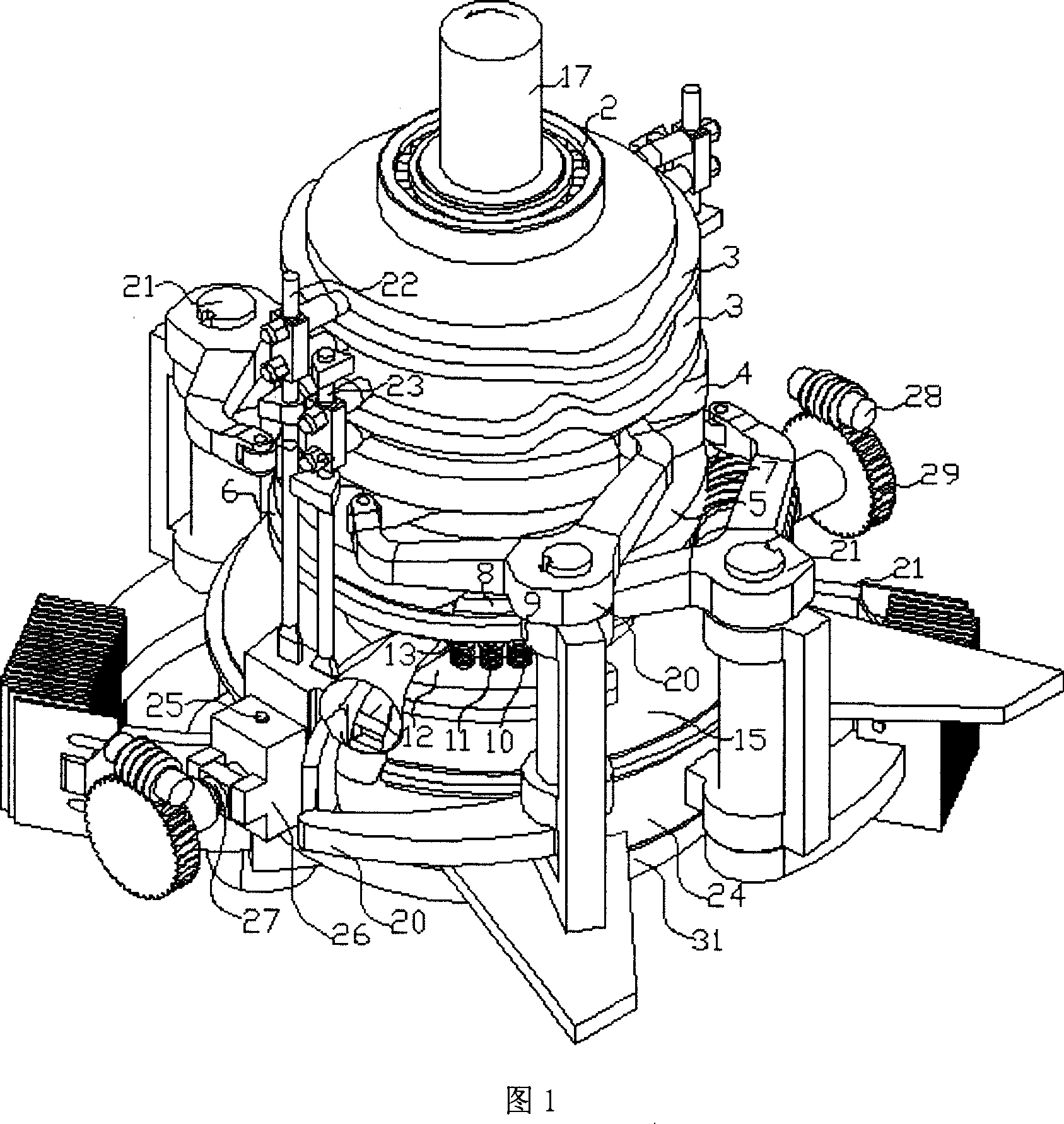
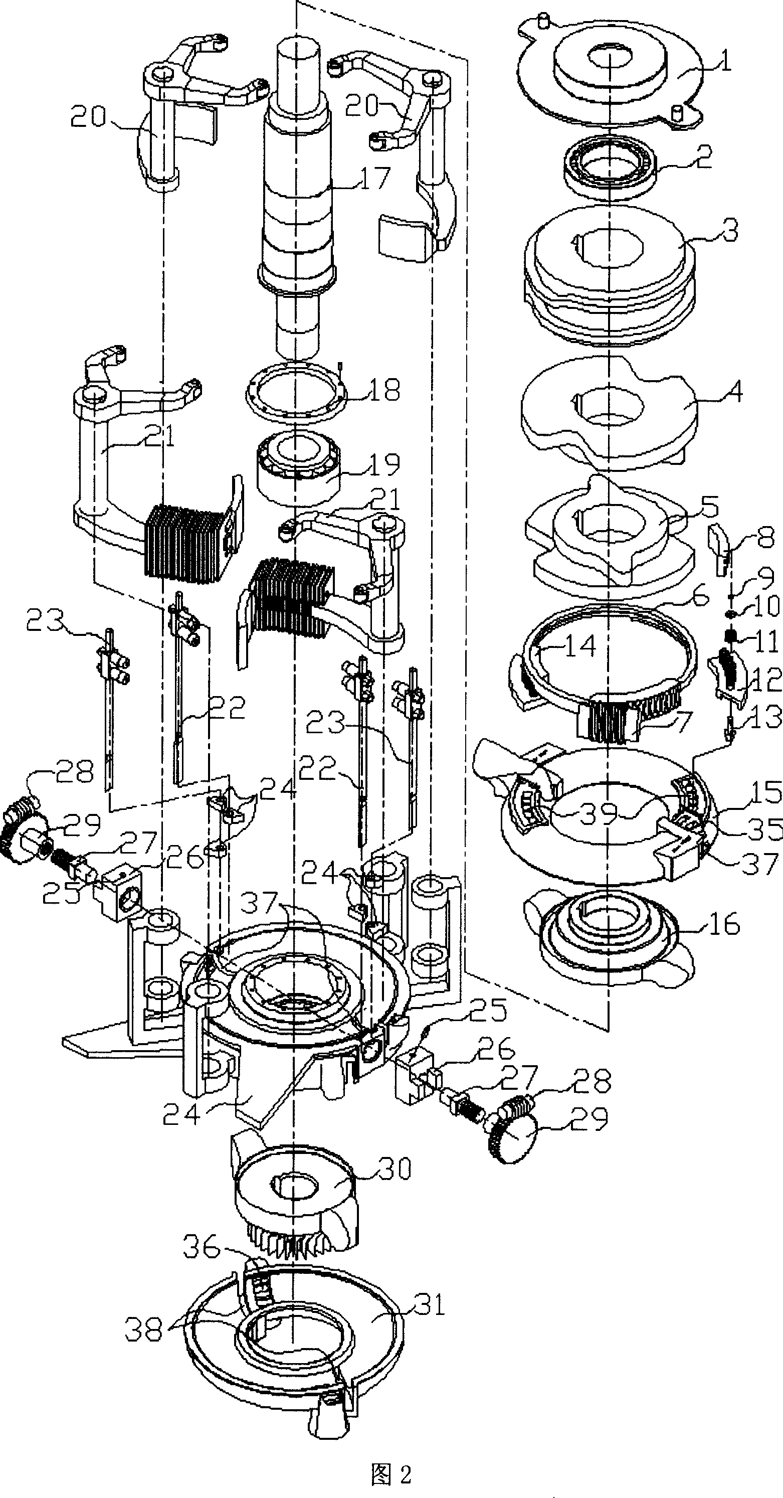
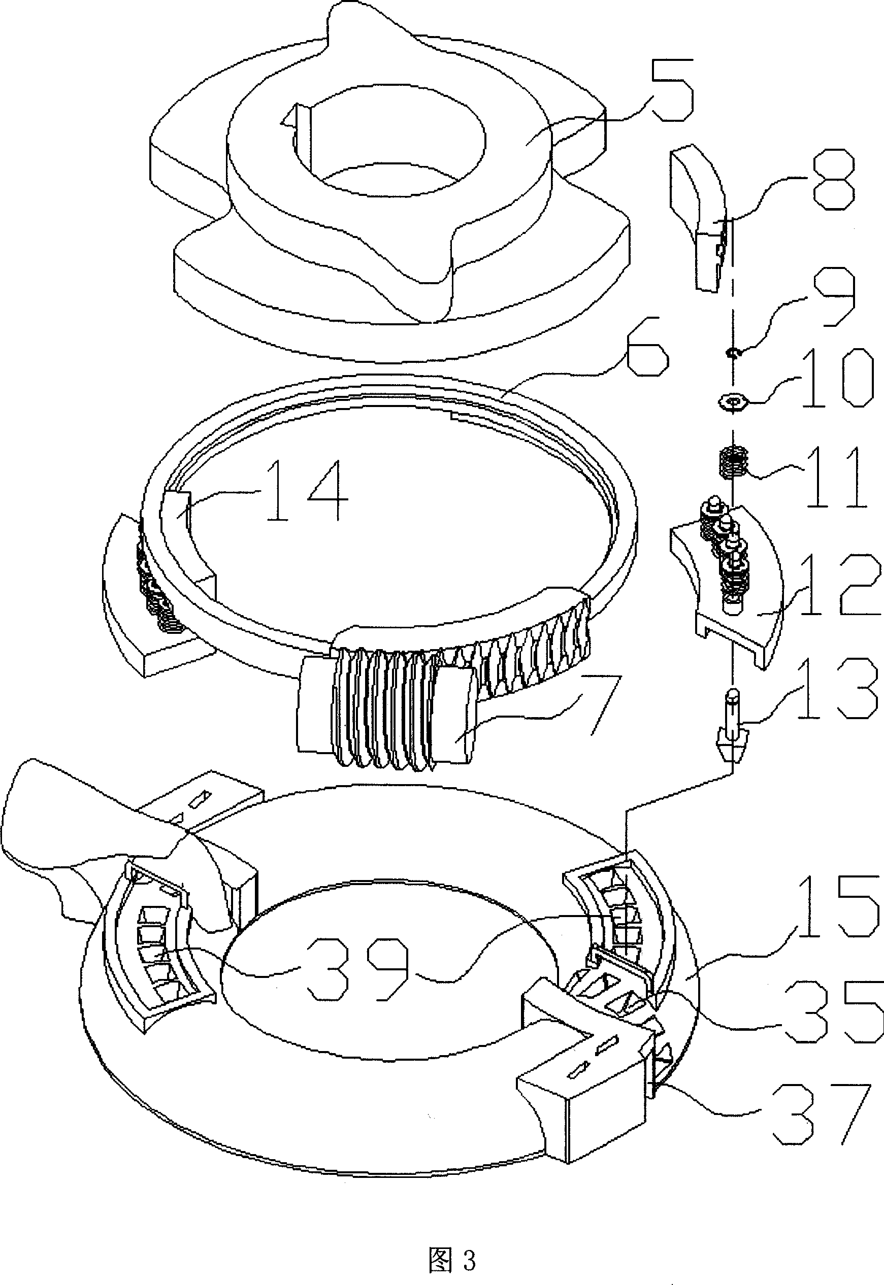
[0092] The engine shaft completes N per revolution2 Secondary air intake (N is the number of protruding pistons of the compression disk or work disk), compression, combustion work, exhaust cycle, each cycle is the same. The following is an example of an engine with two protruding pistons per disk.

[0093] As shown in Figures 1 to 5:

[0094] 1. The main shaft (17) is fixed with the compression valve and the work valve drive cam (3), the compression ring slider drive cam (4), the work ring slider drive cam (5), the compression disc (16), the work disc (30 ), the main shaft is supported by the bearing (2) and the double-row tapered roller bearing (19), which bears the radial and axial loads of the main shaft, and the middle ring (24) and the bearing pressure plate (18) fix the double-row tapered roller bearing, Bearing (2) is fixed on the end cover (1).

[0095] 2. The C-shaped annular cavity formed by the compression half ring (15) and the middle ring (24) has an opening tow...


PUM


Abstract

The rotating engine consists of mainly two, one large and one small, C-shaped annular cylinder liners and one piston to form two D-shaped annular spaces, one cylindrical cylinder liner to communicate these two annular spaces, two pistons on two ends of the cylindrical cylinder liner, one radial sliding block contacting to one disc, and one cam link mechanism to drive the sliding block. The small annular cylinder liner is provided with air inlet, and large one with exhaust port. With the rotation of the disc, the sliding of the sliding block and the rotation of the pistons inside the cylinder liner, the cycle including admission, compression, expansion and exhaustion is completed. The rotating engine has high mechanical efficiency and heat efficiency, simple structure, small size, light weight, low noise, less exhaustion and long service life.

Description

Technical field: [0001] The invention relates to an internal combustion engine. technical background: [0002] In 1883, Gottlieb Daimler made the first four-stroke reciprocating piston gasoline engine, and in 1897, Diesel diesel engine. So far, the internal combustion engine has always been dominated by the reciprocating piston type, and various rotary engines have also appeared. Due to the problems of sealing, power transmission mechanism and service life of rotary engines, there are many kinds of rotary engines and cannot be industrialized. The triangular rotor engine is more widely used, but it cannot be popularized due to problems such as fuel economy and emissions. [0003] The disadvantages of reciprocating piston internal combustion engines are: [0004] 1. Due to the reciprocating inertial force and moment of inertia caused by the reciprocating mass, it cannot be completely balanced. When the rotation speed increases, the unbalanced force and moment increase shar...

Claims


Application Information

Patent Timeline
IPC IPC(8): F02B53/02F02B53/06
CPCY02T10/17Y02T10/12
Inventor 陈崟
Owner 陈崟
Learn More