Micro jet flow cooling system for electronic device

A technology for electronic devices and cooling systems, applied in the cooling of instruments, electrical solid devices, electrical components, etc., can solve the problem that the cooling method of large heat flux cannot reach the ideal, and achieve the effect of high heat transfer coefficient and flexible control

Inactive Publication Date: 2007-07-25
刘胜
View PDF0 Cites 32 Cited by
  • Summary
  • Abstract
  • Description
  • Claims
  • Application Information

AI Technical Summary

Problems solved by technology

[0003] But at present, in high-performance supercomputers and military avionics equipm

Method used


Image

  • Micro jet flow cooling system for electronic device
  • Micro jet flow cooling system for electronic device

Examples


Embodiment 1

[0014] Embodiments of the present invention are further described below in conjunction with the accompanying drawings:

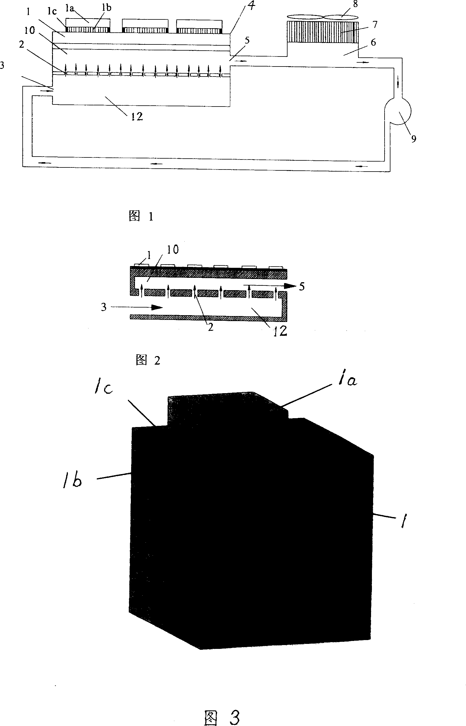
[0015] Referring to Fig. 1, Fig. 2, Fig. 3, the base 1 of the electronic components and parts of the present embodiment is a computer chip CPU1a, and the computer chip CPU 1a is installed together with the base 1 of the electronic device by connecting the welding post 1b, and the computer chip CPU 1a With thermal diffusion column 1c. The lower surface of the base 1 of the electronic components is tightly mounted on the shell of the micro jet 4, and the micro jet 4 is made of carbon nanotubes, high thermal conductivity metal, diamond and other high thermal conductivity materials. A heat conduction paste is added between the outer surface of the micro jet and the lower surface of the base of the CPU to increase the heat conduction effect and reduce the heat resistance. The micro-jet flow device 4 is provided with two cavities, the upper cavity 10 and the lowe...

Embodiment 2

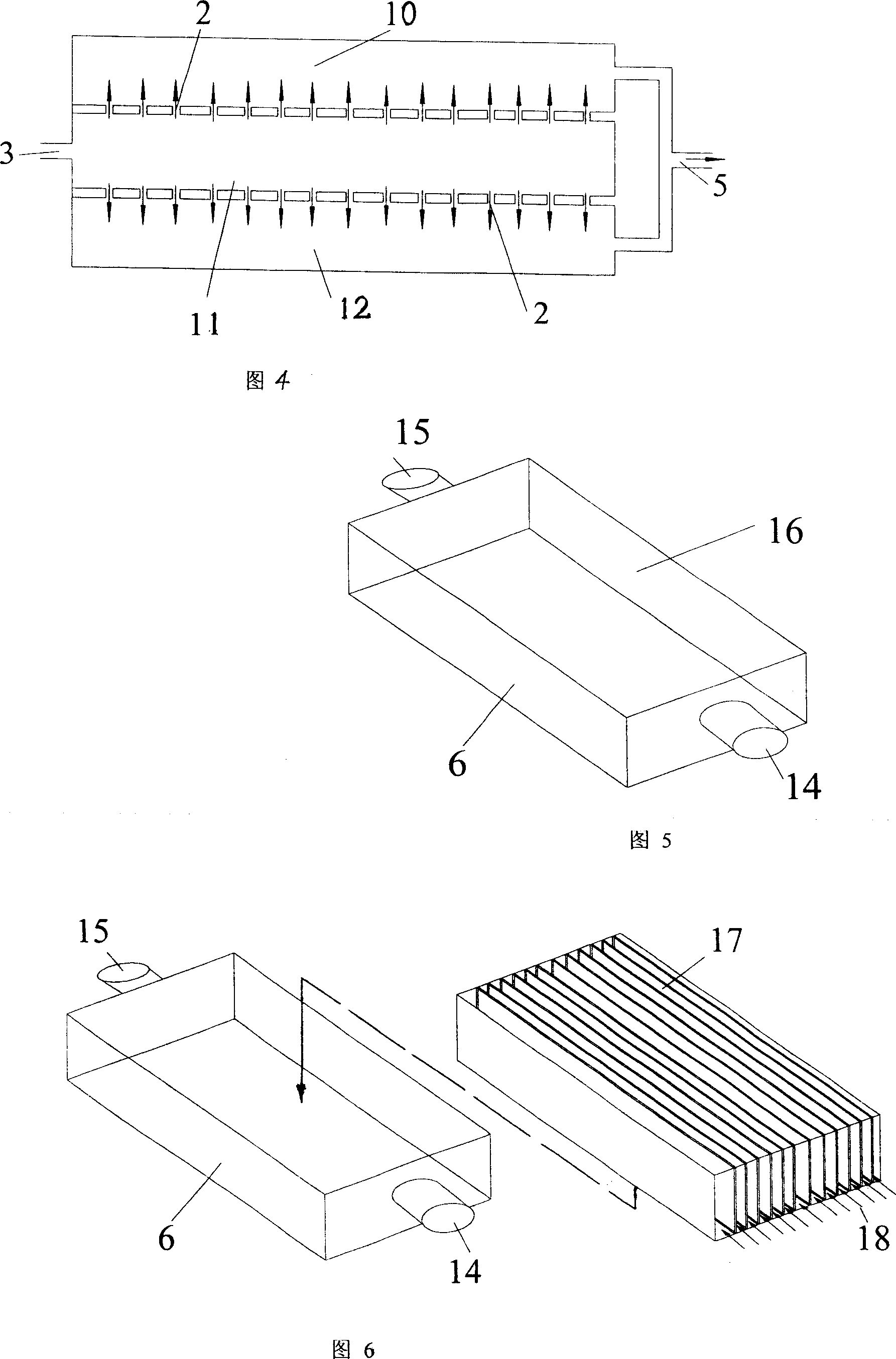
[0019] Embodiment 2 is the same as Embodiment 1, except that Embodiment 1 adopts the middle of the chamber of the micro-jet fluidizer to be divided into upper and lower chambers 10, 12 by a partition plate 2 with a plurality of micro-nozzles 21. . And embodiment 2 is divided into upper, middle and lower three cavities 10, 11, 12 by two partitions 2 with a plurality of micro nozzles. See Figure 4. Liquid or gas flows in from the cooling medium inlet 3 of the micro jet, and the liquid or gas enters the middle cavity 11 of the micro jet cavity, and under the action of pressure, the liquid or gas forms a jet at the micro nozzles 21 on both sides , the inner side of the contact surface of the micro jet that is closely connected to the lower surface of the base 1 of the impact electronic device, the liquid or gas after heat exchange flows out from the lower cavity 12 and the upper cavity 10 respectively and merges in the micro jet Cooling medium outlet 5, re-enter the main pipelin...


PUM


Abstract

The system comprises: a chip of electron device; a micro jet-stream appliance, a liquid reserve tank with a cooling unit, and a micro pump. It features the following: the cooling media uses liquid or gas, and is cycled to form a closed cooling system; on the top of the liquid reserve tank there is a fan and a heat-sink installed; the liquid reserve tank is connected to the micro pump and micro jet-stream appliance; there are multi chambers set in the jet-stream appliance; between the chambers there are separators; the chip of electron device is mounted on the micro jet-stream appliance.

Description

technical field [0001] The invention relates to a cooling system for electronic devices, in particular to a micro jet cooling system for electronic devices. technical background [0002] The essence of the working process of any electronic device is the energy conversion process, which is always accompanied by heat generation. The root cause of heat generation is that any energy conversion process cannot be 100% efficient, and all or most of the energy that is less than 100% becomes heat. Existing electronic devices are developing in the direction of smaller, higher speed, and higher power density, which means greater heat flux density. Supercomputers are mainly composed of high-power density electronic components such as microprocessors and control circuits. The density is very high, on the order of 100W / cm 2 around or higher. Due to volume limitations, high-performance servers and notebooks also have a very high heat flux density. In order to maintain normal work, their...

Claims


Application Information

Patent Timeline
IPC IPC(8): H05K7/20H01L23/473G06F1/20G12B15/02
Inventor 刘胜罗小兵
Owner 刘胜
Why Eureka
Try Eureka