
A novel optical fiber grating temperature compensation encapsulation method

A fiber grating and temperature compensation technology, applied in optical fiber transmission, electromagnetic wave transmission systems, electrical components, etc., can solve problems such as temperature coefficient of 1pm/℃, complex packaging structure, increased polarization mode dispersion, etc., and achieve long-term wavelength stability , good long-term temperature characteristics, good effect of temperature characteristics

Inactive Publication Date: 2007-08-01
BEIJING JIAOTONG UNIV
View PDF0 Cites 14 Cited by
  • Summary
  • Abstract
  • Description
  • Claims
  • Application Information

AI Technical Summary

Problems solved by technology

The packaging method reported in Document 1 (Temperature-stabilized metal packaging of fiber gratings, Journal of lightwave technology, 2003, 21(5): 1377-1383) does not require prestressing, but requires a metal layer, the process is complicated and the length of the package Longer, and the temperature coefficient is still 1pm / ℃
Document 2 (A fiber grating probe with temperature compensation, Optical Fiber Sensors Conference Technical Digest, 2002, 1(15): 347-350) reports that the structure of the packaging method is relatively complicated and the temperature coefficient is about 1.5pm / °C
Although the packaging method reported in Document 3 (Temperature Compensation of Fiber Bragg Grating, Acta Optics Sinica, 2003, 2003, 23(6): 677-679) has a simple structure, it may cause the grating to Changes in characteristics, such as an increase in polarization mode dispersion, and the temperature coefficient is still 1.7pnm / °C
In addition, some commercial fiber gratings are packaged in ceramics, which are not only expensive and bulky, but also fragile when touched.

Method used


Image

  • A novel optical fiber grating temperature compensation encapsulation method
  • A novel optical fiber grating temperature compensation encapsulation method

Examples


Embodiment Construction

[0017] The present invention will be further described below in conjunction with the accompanying drawings and specific embodiments.

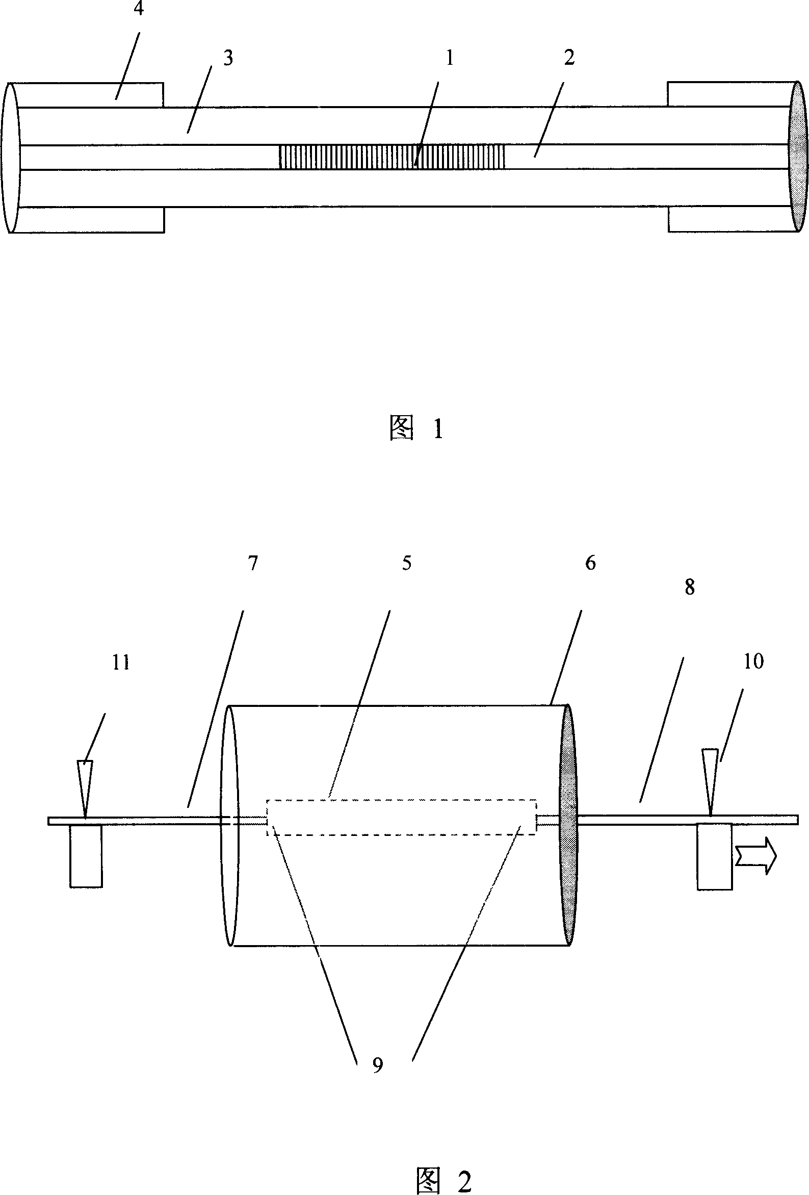
[0018] First of all, in order to make the fiber grating have stable performance, it must be annealed at high temperature for a long time. The structure of the fiber grating written on the photosensitive optical fiber is shown in Figure 1, and the coating layer of the writing grating part must be removed. After the written fiber grating is annealed, the bare optical fiber part where the fiber grating is written should be protected by coating.

[0019] The second is to make an encapsulating tube with a negative coefficient of thermal expansion. The negative thermal expansion coefficient of the packaging tube is closely related to the production temperature. In order to make the packaged tube just completely compensate for the wavelength drift of the fiber grating, in the process of manufacturing the packaging tube, the high-temperature heat trea...


PUM


Abstract

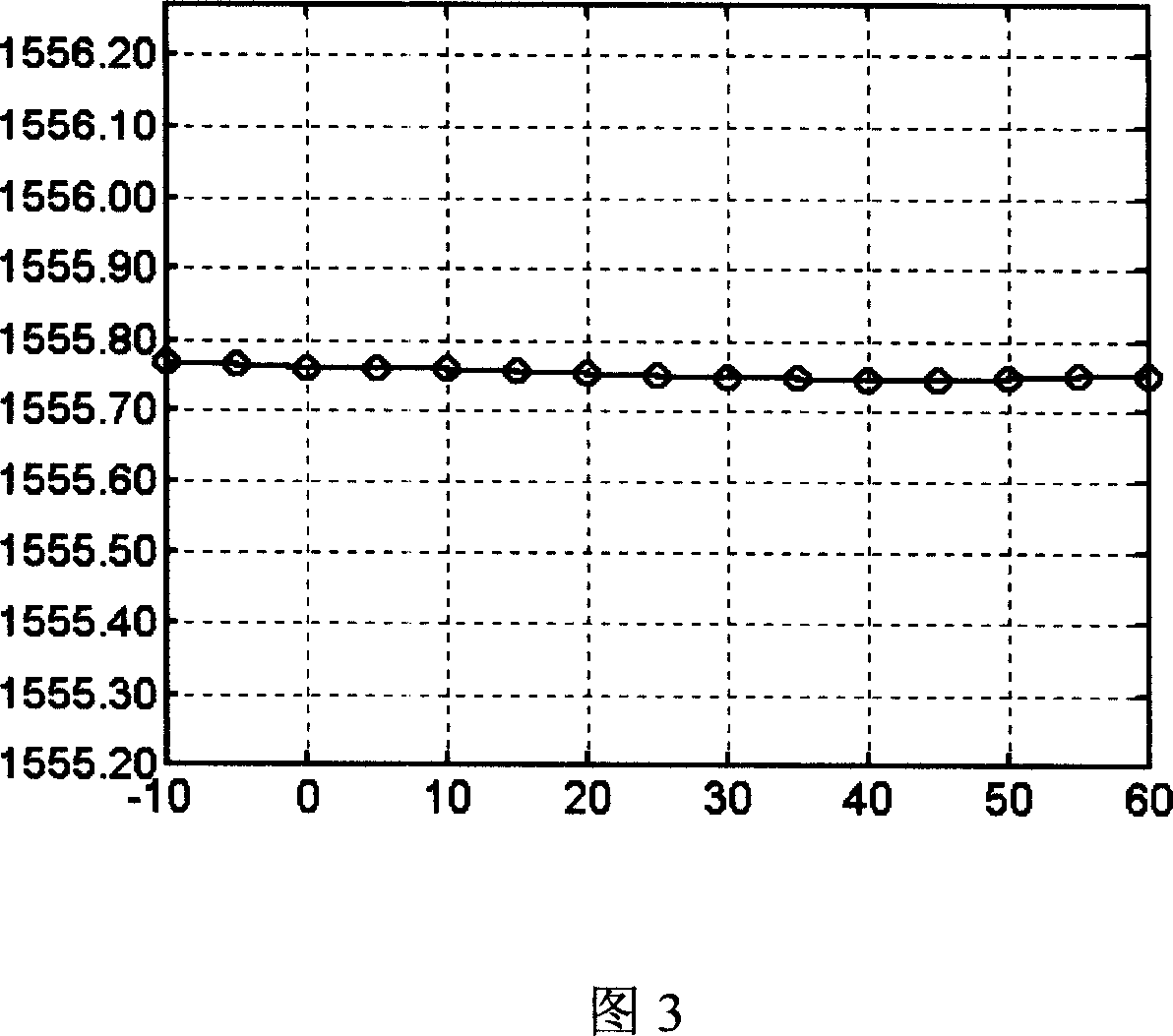
The invention discloses a method of compensating fiber grating temperature coefficient with encapsulation cannula which possesses negative temperature coefficient. A material which does not possess negative temperature coefficient is used to produce encapsulation cannula with tiny negative heat expansion coefficient by special process; it can completely compensate the wavelength shift generated by change of temperature. The encapsulation cannula encapsulates the fiber grating quickly under the high temperature to produce fiber grating which is not sensitive to temperature and possesses high heat stability, and it is high and low temperature circle aged for multiple times. The invention is simple, cost is low, more important is that the temperature performance is well, the temperature coefficient of fiber grating can achieve 0.0005nm / DEG C under the circumstance of -10DEG C to 60DEG C, and it possesses perfect long time temperature property. The column of the fiber grating encapsulated is small, the weight is light, shock resistance property is strong, and it is an ideal encapsulation method for fiber grating.

Description

technical field [0001] The invention relates to a method for optical fiber grating temperature compensation packaging, which belongs to the technical fields of optical fiber communication, optical fiber sensing and optical fiber devices. Background technique [0002] The appearance of Fiber Bragg Grating (FBG) is considered to be another event of great significance in the field of optical fiber communication after the appearance of Erbium-doped fiber amplifier (EDFA). FBG is widely used in various fields of optical fiber communication and has broad application prospects. [0003] Since FBG is realized through the modulation of the refractive index along the axis of the fiber, when the external temperature changes, the refractive index of the fiber and the size of the fiber will change, resulting in the change of the fiber grating written on the fiber. This will cause the wavelength of the FBG to change with temperature, and the temperature coefficient of the unpackaged fiber...

Claims


Application Information

Patent Timeline
IPC IPC(8): H04B10/12H04B10/18H04B10/25
Inventor 简伟延凤平郭铁英刘利松王燕花
Owner BEIJING JIAOTONG UNIV
Learn More