Serous fluid distributor

A distributor and slurry technology, applied in the field of slurry distribution devices, can solve the problems of difficult sulfur dioxide emissions, large differences, and small capacity of a single machine, etc., and achieve the effects of easy process manufacturing, novel and scientific conception, and convenient control

Inactive Publication Date: 2007-08-08
SHENYANG HEAVY MACHINERY GROUP
View PDF0 Cites 1 Cited by
  • Summary
  • Abstract
  • Description
  • Claims
  • Application Information

AI Technical Summary

Problems solved by technology

In my country's high-sulfur coal production areas, the organic sulfur content in coal is relatively high, and it is difficult to effectively control sulfur dioxide emissions by coal washing methods
Clean coal combustion technology is a new technology developed in the past 10 years in the world. Although mature commercial technology has been developed in industrialized countries, the capacity of a single unit is not large; and clean coal co

Method used


Image

  • Serous fluid distributor
  • Serous fluid distributor

Examples


Embodiment Construction

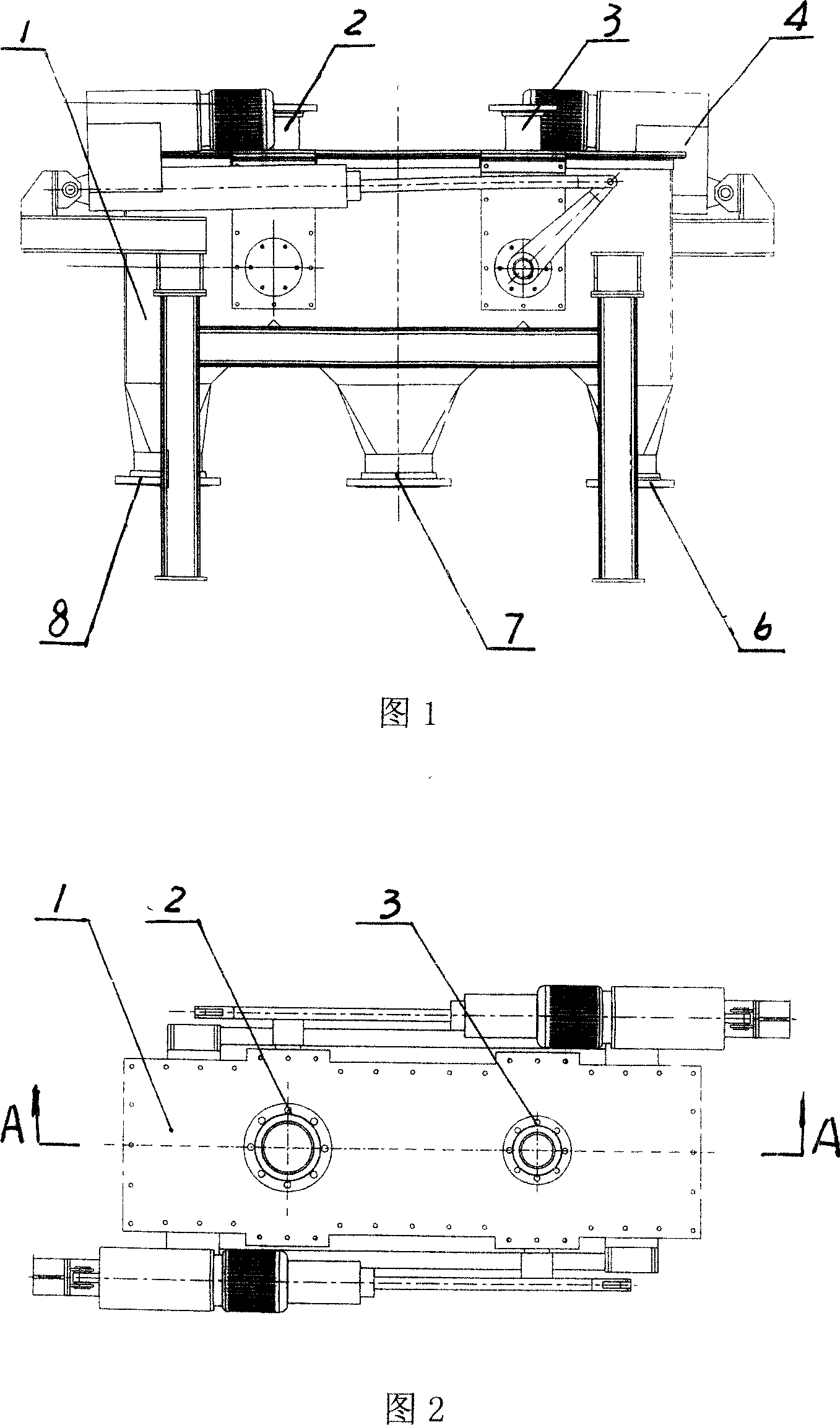
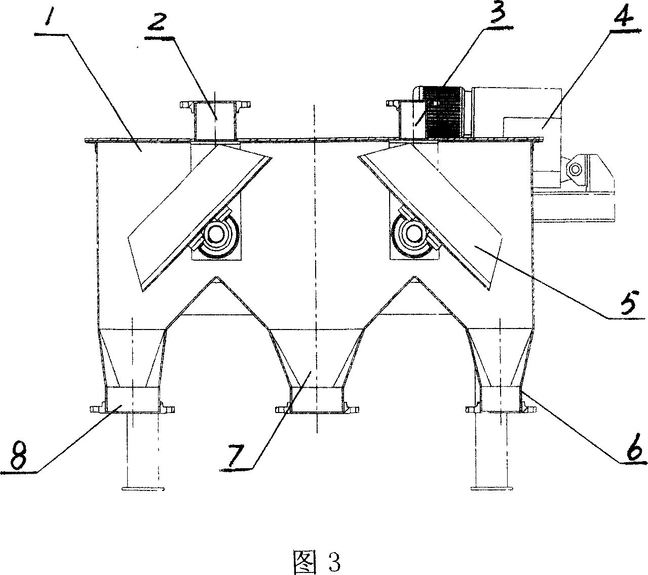
[0012] The slurry distributor is composed of a box body 1, a first flange 2, a second flange 3, an electric actuator 4, a flap device 5, a third flange 6, a fourth flange 7, and a fifth flange 8. The first flange 2 and the second flange 3 are arranged on the upper side of the box body 1, electric actuators 4 are respectively installed on both sides of the upper side of the box body 1, two flap devices 5 are installed in the box body 1, and a The third flange 6 , the fourth flange 7 , and the fifth flange 8 . The operation mode of the slurry distributor is to control the action of the turnover device 5 through the electric actuator 4, and send the slurry to the liquid storage tank of the desulfurization tower, the entrance of the mill and the recirculation device, and the first flange 2 above the box body 1 and the second flange 3 are respectively connected to the corresponding flanges of the slurry separation device. Two flap devices 5 are installed in the box body 1. Accordin...


PUM


Abstract

A slurry distributor used in electric industry comprises a box, a first flange, a second flange, an electric executor, a turnover plate, a third flange, a fourth flange, and a fifth flange. The third, fourth and fifth flanges are arranged under the box. The operation comprises that the electric executor controls the turnover plate to feed the slurry to the liquid pot of the desulfuration tower, the inlet of abrading machine and the circulator. The first and second flanges above the box are connected to the flanges of slurry separator. The box is mounted with two inner turnover plates, to change the direction of slurry. The executor via the pressure and density signals of checker controls the turnover plates, to realize automation. The invention has simple structure and easy control.

Description

Technical field: [0001] The invention relates to a high-efficiency and durable slurry distribution device in a desulfurization pulping system in the electric power industry, which can effectively and quickly respond to system requirements and meet the needs of desulfurization technology, and is especially widely used in power plant flue gas desulfurization projects. Background technique: [0002] At present, domestic and foreign power plants mainly use thermal power to generate electricity. The flue gas produced by the combustion of coal (such as other fuels) contains a certain amount of some harmful gases such as SO2, which seriously pollutes the atmospheric environment and destroys the ecological environment. my country's resources are seriously insufficient and the ecological environment is severe. Sulfur dioxide pollution in the air is serious in many cities in my country. In recent years, the acid rain pollution situation in the country has not improved significantly, a...

Claims


Application Information

Patent Timeline
IPC IPC(8): F16K11/052B01D53/80
Inventor 单东升杨丽杰
Owner SHENYANG HEAVY MACHINERY GROUP
Why Eureka
Try Eureka