Cast-in-situs steel reinforced concrete raceway water pressure testing method
A reinforced concrete and hydrostatic test technology, which is applied in the direction of applying stable tension/pressure to test the strength of materials, and using liquid/vacuum degree to measure liquid tightness, etc., which can solve the difficulty of lifting the sealing plate and poor sealing operation conditions , tight construction period and other issues, to achieve the effect of easier guarantee of safety and quality, easy operation and low cost
- Summary
- Abstract
- Description
- Claims
- Application Information
AI Technical Summary
Problems solved by technology
Method used
Image

Examples
Embodiment Construction
[0045] The embodiment of the segmental hydrostatic test of the cast-in-place reinforced concrete water pipe of the present invention: the above-mentioned water pipe is a connection form assembled in sections, and the steps of the hydraulic test method are as follows:
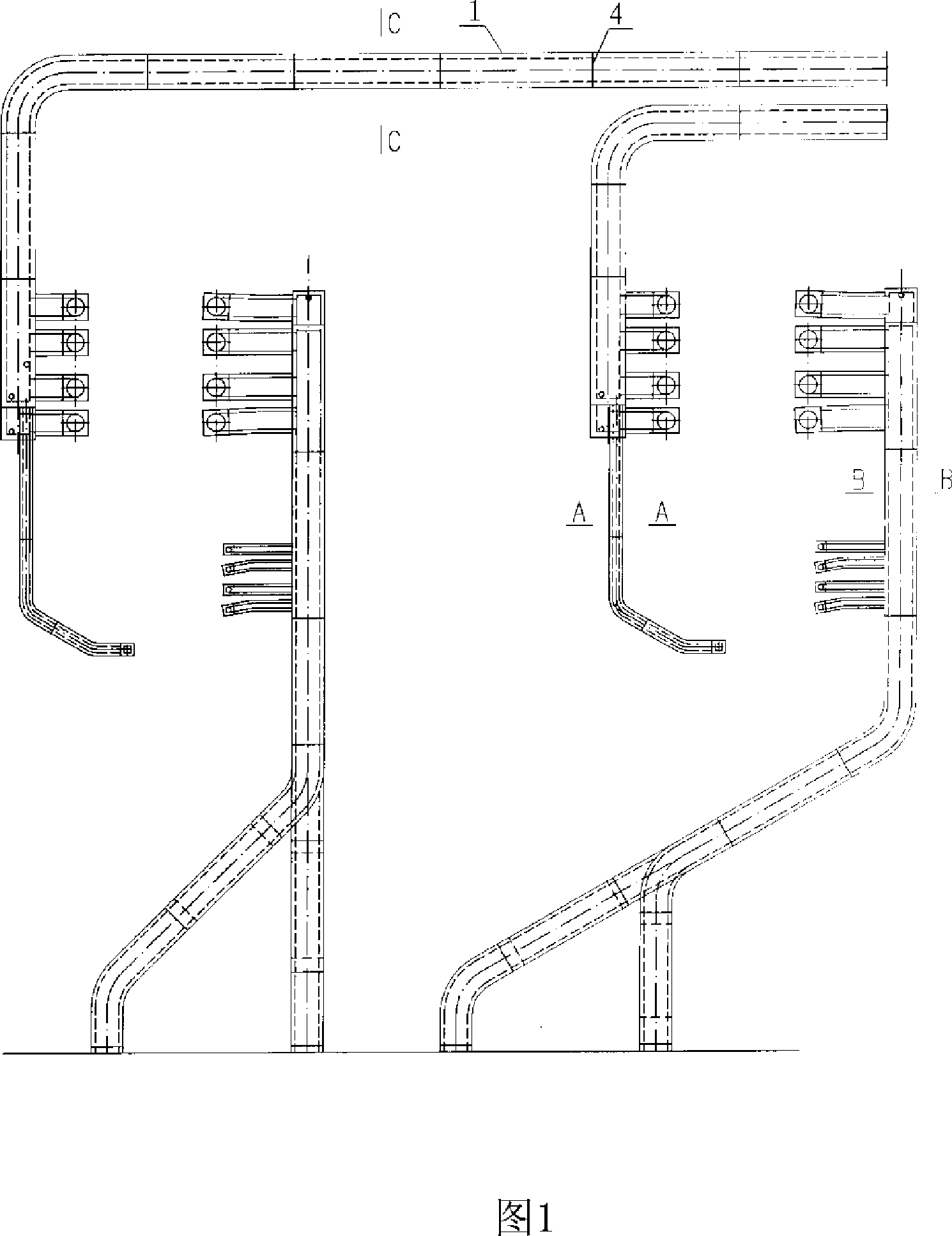
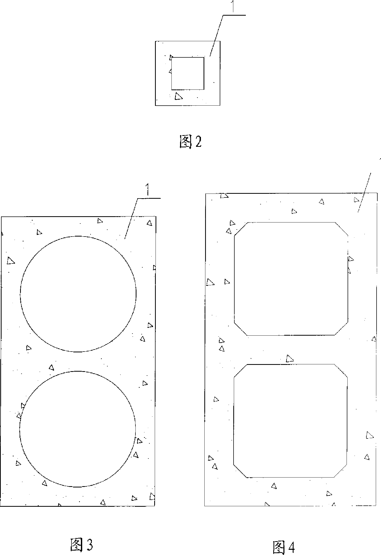
[0046] See Figure 1-4 for step 1, construct the reinforced concrete water pipe, the shape of the reinforced concrete water pipe 1 can be a square tube with a square hole, as shown in Figure 2; it can also be a square tube with a round hole, as shown in Figure 3; or a square tube with a polygonal shape Hole shape, as shown in Figure 4; it can be single hole or double hole.
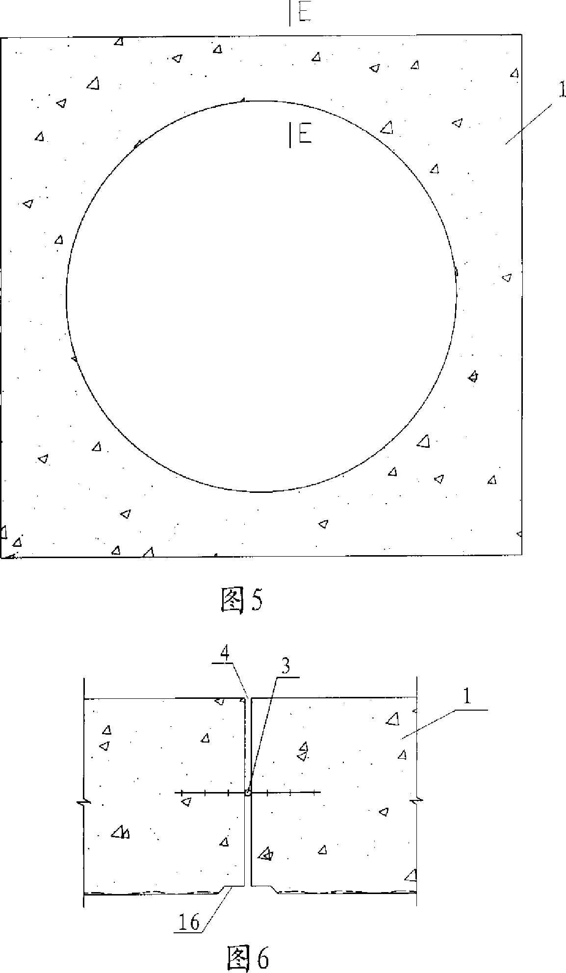
[0047] Step 2 Referring to Figures 5 and 6, the inner wall of the reinforced concrete water pipe 1 is cleaned and repaired to make it smooth. A waterstop 3 is arranged in the expansion joint 4 at the pipe joint, and a circle of notches 16 is reserved on the inner wall of the pipe head at the expansion joint.
[0048] Step 3, see Figure 11, a...
PUM
 Abstract
Description
Claims
Application Information
 - R&D
- Intellectual Property
- Life Sciences
- Materials
- Tech Scout
- Unparalleled Data Quality
- Higher Quality Content
- 60% Fewer Hallucinations
Browse by: Latest US Patents, China's latest patents, Technical Efficacy Thesaurus, Application Domain, Technology Topic, Popular Technical Reports.
© 2025 PatSnap. All rights reserved.Legal|Privacy policy|Modern Slavery Act Transparency Statement|Sitemap|About US| Contact US: help@patsnap.com