Light source even optical fibre low-waste conduction projector

A technology for optical devices and light sources, applied in the directions of light guides, electric light sources, lighting devices, etc., can solve the problems of limited installation location, weak luminous intensity, and reduced optical signal quality.

Active Publication Date: 2007-08-08
HENAN COSTAR GRP CO LTD +1
View PDF0 Cites 6 Cited by
  • Summary
  • Abstract
  • Description
  • Claims
  • Application Information

AI Technical Summary

Problems solved by technology

Since the light path channel in the structure adopts a box structure, its space cross-sectional area is large, and the light is easy to be lost, so the light intensity of the emitted light beam is easy to attenuate and unevenly distributed during the transmission process; especially the focused image of the light source filament is formed on the light path. Dark spots are brought into the light beam, thus affecting the stability of the monitoring light signal and the accuracy of the monitoring results
At the same time, the modulator in the optical path often causes uneven rotation speed of the power motor and the modulation disc driven by the fluctuation of the power supply voltage, which causes random fluctuations in the wavelength and frequency of the modulated beam, which reduces the quality of the optical signal and is difficult to distinguish
Secondly, the optical hole on the modulation disc is generally circular or fan-shaped, and the modulated light is a wave that approximates a trapezoidal curve. Its peak value is not easy to distinguish, and harmonic noise is generated, which adversely affects the monitoring sensitivity of the signal.
In addition, the luminous light source generally adopts an incandescent bulb, and a flat or curved reflector lampshade is used. The luminous intensity is weak and there is no convergence. And cause the light signal of the monitoring system to be weak, the monitoring and identification is difficult, and the effect is poor
Third, the conductive components of the existing monitoring technology are closely connected to ensure the linear transmission of the optical path. Therefore, the installation on the coating machine takes up a lot of space, which limits the installation position and is inconvenient for installation and maintenance.

Method used


Image

  • Light source even optical fibre low-waste conduction projector

Examples


Embodiment Construction

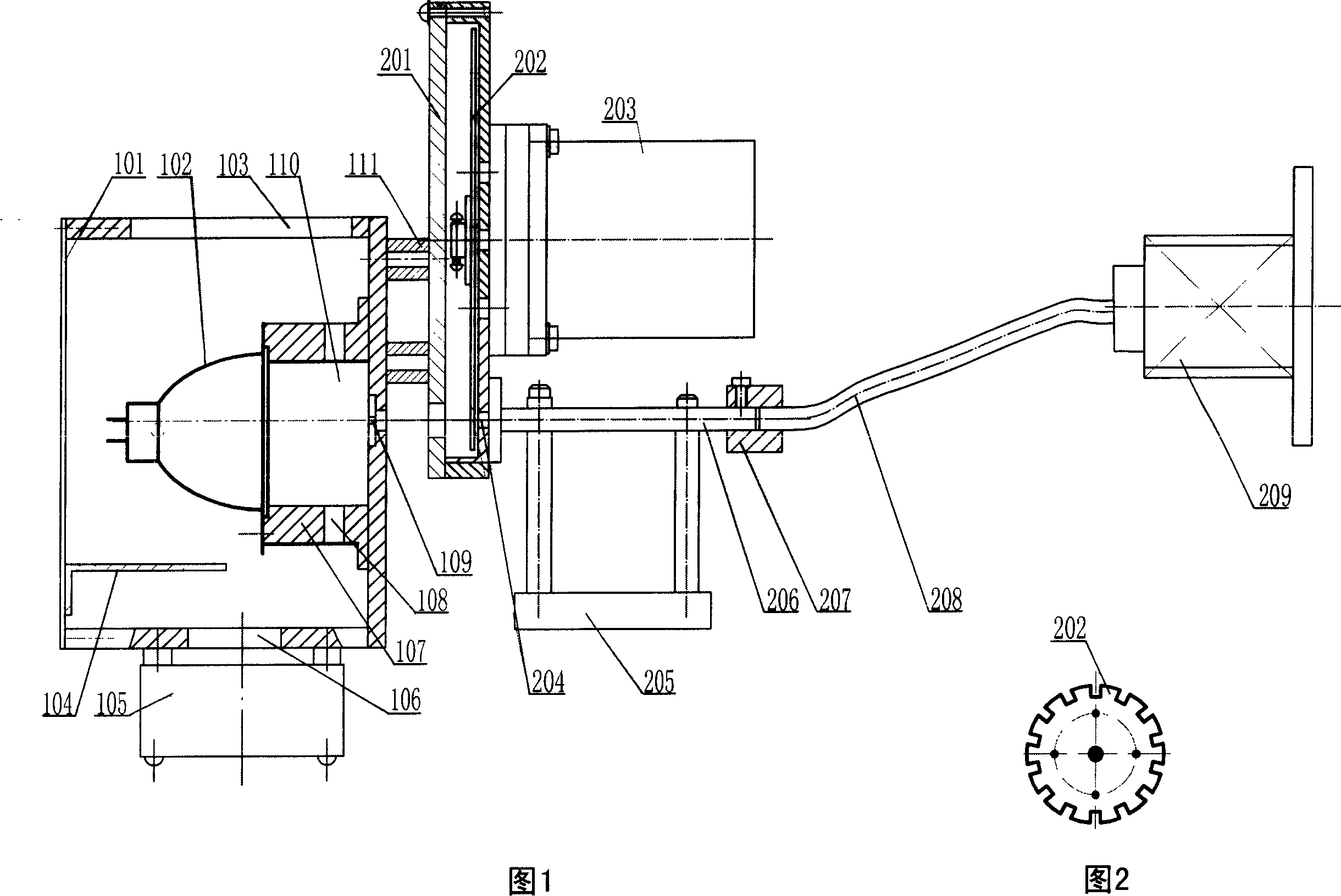
[0014] Referring to Fig. 1 and Fig. 2, the light source uniform light optical fiber low-loss transmission light projection device of the present invention is composed of a light source emission box, a modulator, and a light transmission component, wherein the front wall of the light source emission box 101 is provided with a light source for emitting light beams The exit hole 109 is provided with a high-brightness halogen tungsten lamp 102 capable of producing a strong light source inside. The halogen tungsten lamp 102 is composed of a halogen tungsten lamp, a spotlight cover with an ellipsoid and a lamp holder 107, wherein the lamp holder 107 is fixed on On the front inner wall of the light source emitting box body 101 , the center of the lamp holder 107 is a hollow cavity with a light channel 110 , and communicates with the light source exit hole 109 provided on the front wall of the light source emitting box body 101 . The concentrating surface of the spotlight cover faces t...


PUM


Abstract

The invention is a light source uniform low loss transmission projecting device used in the optical coating monitoring system, and it comprises the light source firing box, the modulator, the optical component, in which, the light source firing box has the tungsten lamp with spotlight cover, one side of the box connecting with a fixed speed motor modulator through the supporting pillar, the outer light hole of the modulator correspondingly connecting with a uniform light rod of horizon position with the same axis as the firing axis, and the light output connecting with the fiber for transmitting the optical beam by the fixture, the other end of the fiber connecting with the fiber connector block. The device can not only generate high-brightness strong light source, but modulation light output stable, and it can make the light source lamp issuing the high brightness light to effectively and uniform transmit, and passing the uniform light rod and optical fiber transmission, it can effectively avoid the issued beam carrying dark spots due to the imaging of filament on the issued axis, and thus, obtain the uniform light transmission effect with no beam spot and light beam uniform.

Description

technical field [0001] The invention belongs to the technical field of optical coating, in particular to a light source uniform light optical fiber low-loss transmission light projection device used in an optical coating monitoring system. Background technique [0002] In the optical coating film thickness monitoring system, the brightness, uniformity and state of the light wave curve of the light transmission projection beam play an important role in the accuracy of film thickness monitoring. The light transmission device usually used is to project the light beam emitted by the light source on the comparison film directly through the modulation, variable frequency spread and collimation of the focusing lens. Since the light path channel in the structure adopts a box structure, its space cross-sectional area is large, and the light is easy to be lost, so the light intensity of the emitted light beam is easy to attenuate and unevenly distributed during the transmission proces...

Claims


Application Information

Patent Timeline
Patent Type & Authority Applications(China)
IPC IPC(8): G02B1/10G02B6/26G02B1/00G02B27/10F21S2/00F21V13/00F21V29/00F21V11/14F21V8/00F21V29/67F21V29/83G02B1/11
Inventor 赵升林党亚军菊池和夫
Owner HENAN COSTAR GRP CO LTD
Why Eureka
Try Eureka