Fabry-Perotw fiber-optic pressure sensor and manufacture method therefor

A pressure sensor, Perot-type technology, applied in the field of Fabry-Perot-type optical fiber pressure sensors, can solve the problems of difficult demodulation, small air cavity size, difficult signal demodulation, etc., and achieves good reliability and easy production. , the effect of high sensitivity

Inactive Publication Date: 2007-08-15
NANJING NORMAL UNIVERSITY
View PDF0 Cites 40 Cited by
  • Summary
  • Abstract
  • Description
  • Claims
  • Application Information

AI Technical Summary

Problems solved by technology

However, this design also has the following disadvantages: first, the system uses the light intensity demodulation method, and the fluctuation of the light source has a great influence on the solution of the cavity length; second, glass and silicon wafers can also be formed as independent FP cavities Interference signals, and these signals carry useless information, interfere with the useful interference signal formed by the air cavity, and bring difficulties to signal demodulation; third, the size of the air cavity is very small, general

Method used


Image

  • Fabry-Perotw fiber-optic pressure sensor and manufacture method therefor
  • Fabry-Perotw fiber-optic pressure sensor and manufacture method therefor
  • Fabry-Perotw fiber-optic pressure sensor and manufacture method therefor

Examples


Embodiment 1

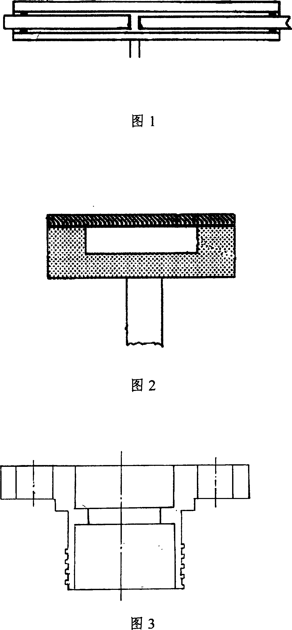
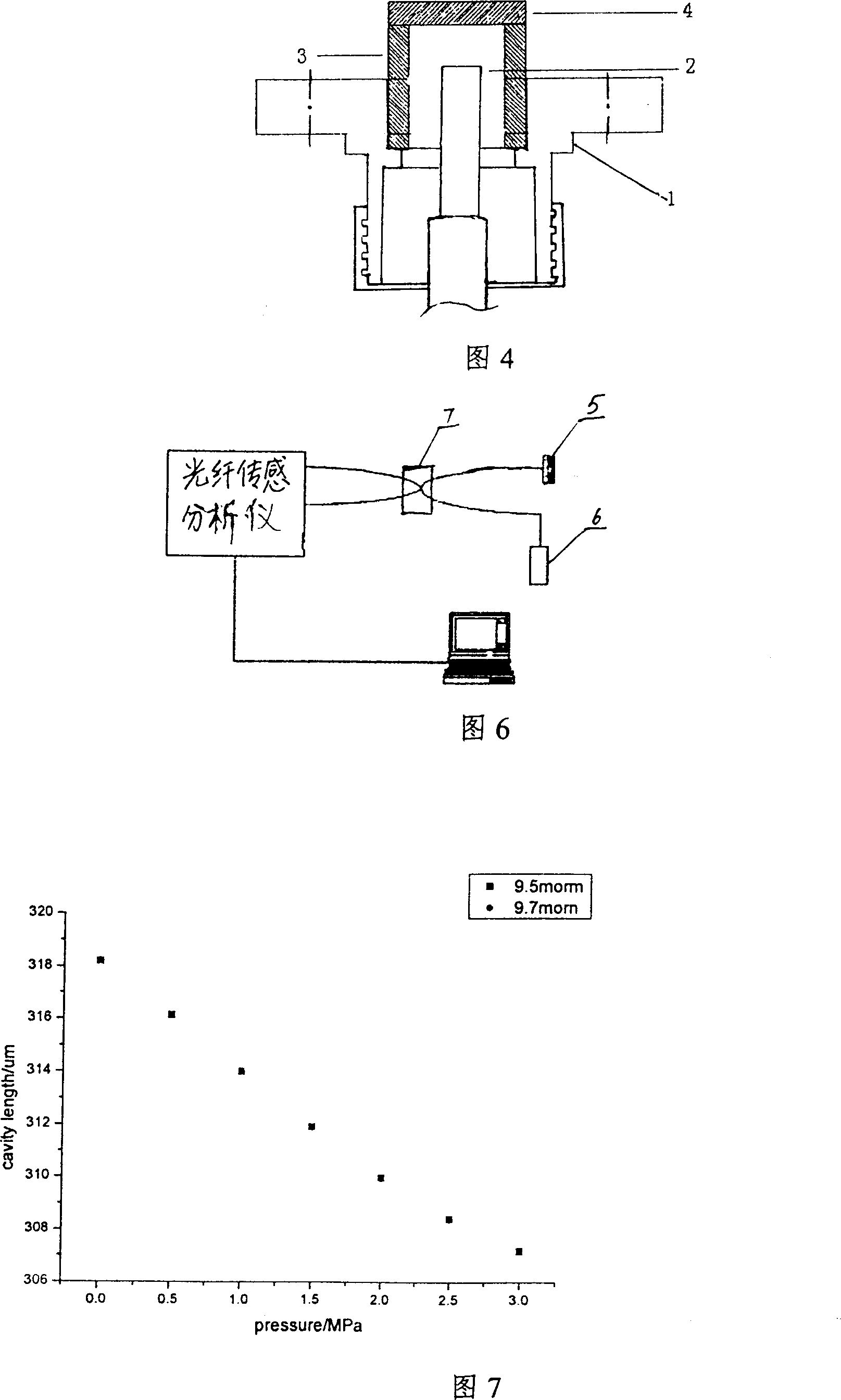
[0032] The silicon is thinned to 180 microns thick by a wet etch method. The glass tube was cut to a length of 3.2 mm, after which both end faces of the glass tube were polished. The glass tube is stacked on the silicon wafer and then placed in the bonding furnace, which is heated to 300°C. The silicon chip is connected to the positive pole, the glass tube is connected to the negative pole, and the voltage is slowly increased to 800V. When the current is zero, take out the glass tube and the silicon wafer, and the two have become one. Place the bonded glass tube in the groove of the FOCI-type optical fiber flange, and fix the side wall with epoxy resin for 24 hours. Screw the FC-PC optical fiber plug to the optical fiber flange (1), the ceramic ferrule (2) on the optical fiber plug and the lower surface of the single crystal silicon wafer (4) form a Fabry-Perot cavity, and finally The sensor is completed by installing the flange plate on the base of the packaging sleeve. ...

Embodiment 2

[0034] The silicon is thinned to 180 microns thick by a wet etch method. The glass tube was cut to a length of 3.2 mm, after which both end faces of the glass tube were polished. The glass tube is stacked on the silicon wafer and then placed in the bonding furnace, which is heated to 300°C. The silicon chip is connected to the positive pole, the glass tube is connected to the negative pole, and the voltage is slowly increased to 800V. When the current is zero, take out the glass tube and the silicon wafer, and the two have become one. Place the bonded glass tube in the groove of the FOCI-type optical fiber flange, and fix the side wall with epoxy resin for 24 hours. Screw the FC-PC optical fiber plug to the optical fiber flange (1), the ceramic ferrule (2) on the optical fiber plug and the lower surface of the single crystal silicon wafer (4) form a Fabry-Perot cavity, and finally The sensor is completed by installing the flange plate on the base of the packaging sleeve. ...

Embodiment 3

[0036] The silicon is thinned to 150 microns thick by a wet etch method. The glass tube was cut to a length of 3.2 mm, after which both end faces of the glass tube were polished. The glass tube is stacked on the silicon wafer and then placed in the bonding furnace, which is heated to 300°C. The silicon chip is connected to the positive pole, the glass tube is connected to the negative pole, and the voltage is slowly increased to 800V. When the current is zero, take out the glass tube and the silicon wafer, and the two have become one. Place the bonded glass tube in the groove of the FOCI-type optical fiber flange, and fix the side wall with epoxy resin for 24 hours. Screw the FC-PC fiber optic plug to the fiber optic flange (1), the ceramic ferrule (2) on the fiber optic plug and the lower surface of the single crystal silicon wafer (4) form a Fabry-Perot cavity, and finally The sensor is completed by installing the flange plate on the base of the packaging sleeve. Lap th...


PUM


Abstract

This invention discloses one Fabry-Perot fiber pressure sensor, which comprises single silicon slice, glass round tube, fiber flange disc and fiber plug and is characterized by the following: the single silicon slice and glass round tube one end are connected through anode keys; other end of round tube is added to fiber flange disc tank; the fiber plug is connected to flange disc with ceramics needle and silicon slice form the chamber. This invention also discloses one method for it, which comprises the following steps: putting the cut glass tube and silicon slice onto key furnace; the glass tube outer wall is coasted with epoxy resin to flange concave tank; connecting the fiber plug into fiber flange disc to form the chamber.

Description

technical field [0001] The invention relates to a Fabry-Perot type optical fiber pressure sensor, in particular to a Fabry-Perot type optical fiber pressure sensor which uses a tunable laser for signal access and uses the wavelength change of the reflection spectrum to complete signal demodulation and its production method. Background technique [0002] Existing Fabry-Perot optical fiber sensors are mainly used to measure strain, such as extrinsic Fabry-Perot interferometers. It is composed of two cut fiber end faces placed in a quartz capillary and an air gap in the middle to form a resonant cavity. Such sensors can only measure the strain of an object and not the pressure. Figure 1 is its basic structure. [0003] Recently, Fabry-Perot type fiber optic sensors for measuring direct pressure have appeared. Figure 2 is a typical structure of it. A thin sheet of silicon covers the glass etched with a shallow cylindrical cavity, and the air cavity between the silicon and t...

Claims


Application Information

Patent Timeline
IPC IPC(8): G01L11/02G01L1/24G01D5/353G02B6/36
Inventor 王鸣陈绪兴葛益娴戎华倪小琦
Owner NANJING NORMAL UNIVERSITY
Why Eureka
Try Eureka