Beam shaping of linear laser diode array and coupling system

A diode array and laser diode technology, applied in the coupling of optical waveguide, nonlinear optics, optics, etc., can solve the problem of difficult surface shape of step mirror processing, and achieve the effect of simple structure, convenient processing and high coupling efficiency

Inactive Publication Date: 2007-08-15
徐州奕创光电科技有限公司
View PDF0 Cites 12 Cited by
  • Summary
  • Abstract
  • Description
  • Claims
  • Application Information

AI Technical Summary

Problems solved by technology

This structure can achieve good shaping and therefore high coupling efficiency, but the disadvantages of this technology are: (1) the optical path unequal between the light fields recombined by the step mirror needs to be compensated; (2) the step mirror It is very difficult to process the surface shape of the mirror, and there is no such processing capacity in China at present

Method used


Image

  • Beam shaping of linear laser diode array and coupling system
  • Beam shaping of linear laser diode array and coupling system
  • Beam shaping of linear laser diode array and coupling system

Examples


specific Embodiment

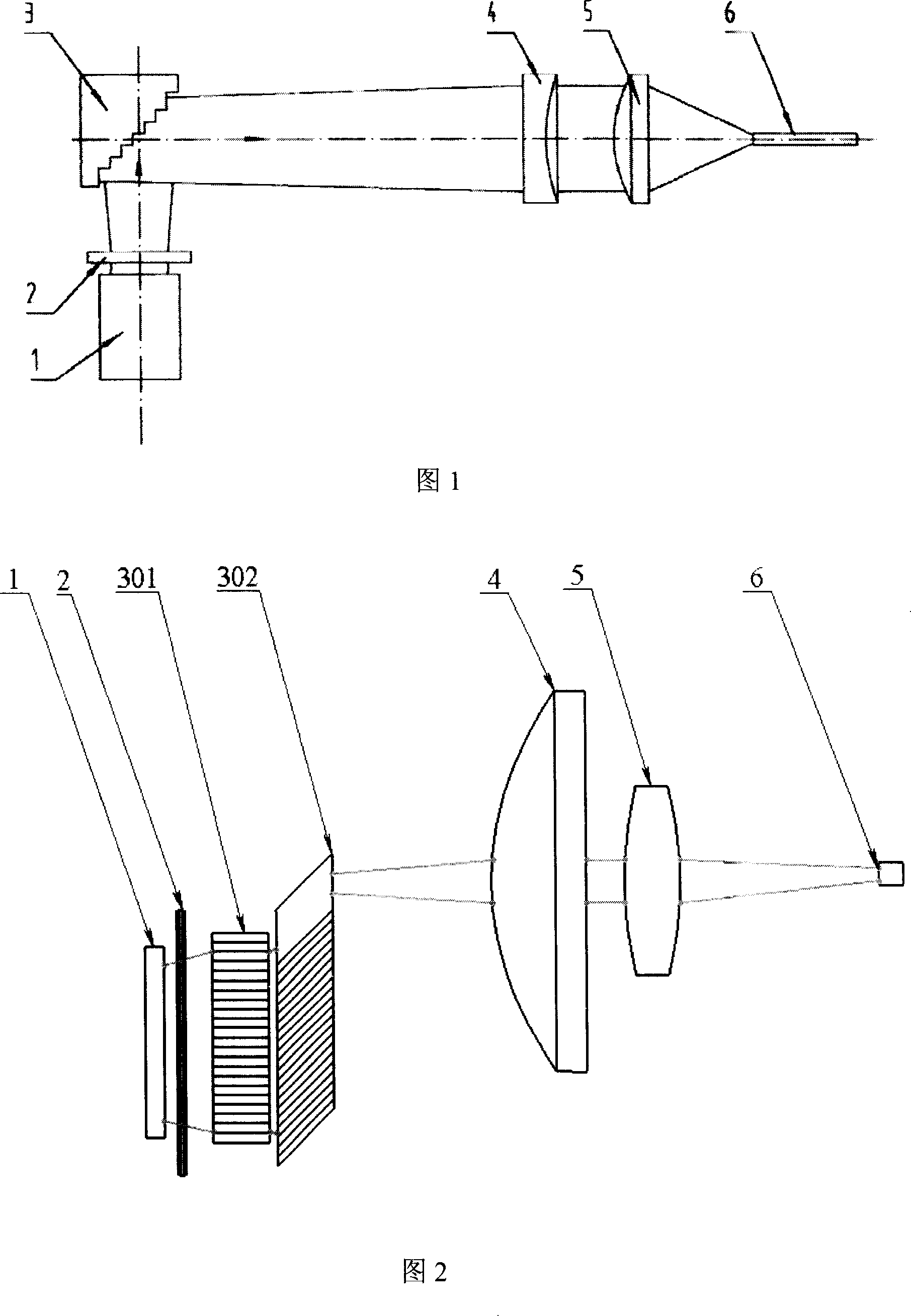
[0026] Use microcylindrical lens 2 to collimate a high-power laser diode array with a length of 1 cm to the direction of the fast axis, and adjust the distance between the microcylindrical lens 2 and the light-emitting surface. Usually, it is not difficult to make the divergence of the fast axis after collimation If the angle is less than 0.5 degrees, the divergence angle in the direction of the slow axis will remain unchanged at this time, about 10 degrees. Considering that the scale of the slow axis increases along with the propagation of the light beam, the distance between the shaper 3 and the microcylindrical lens 2 should be less than 3 millimeters to ensure that the shaper 3 does not need too many microchips to make the linear beam It all goes into the shaper. Shaper 3 is made up of two groups of microchip stacks. Considering that most of the current high-power laser diode arrays are composed of about 20 discontinuous light-emitting regions, each group of microchip stac...


PUM

PropertyMeasurementUnit
angleaaaaaaaaaa
divergence angleaaaaaaaaaa

Abstract

This invention relates to one line laser diode tube array beam rectangle shaping and its couple system, which comprises beams forward direction orderly through micro column lens, parallel micro slice stack shaping device; axis symmetric non-sphere lens and column; the said axis symmetric non-sphere lens and column lens to overlap the beam focus point. This invention relates to line large power light diode array beam couple merge energy transmission fiber for fix laser pump couple.

Description

technical field [0001] The invention relates to beam shaping, in particular to a beam shaping and coupling system of a linear laser diode array, an optical shaping system used for splitting and rearranging the beams emitted by the linear laser diode array, which can output the laser beam emitted by the linear laser diode array After being shaped and coupled into the optical fiber, it can also be used as a pumping coupling system for solid-state lasers. Background technique [0002] The light-emitting surface of the laser diode array is mostly a rectangle of 1×100 μm to 1×400 μm, and the emitted laser beam has different divergence angles in two directions: along the length direction is the slow axis, and the divergence angle is usually 10 degrees; The direction parallel to 1 micron is called the fast axis, and the divergence angle is usually 38 degrees. A high-power laser diode array is formed by arranging discontinuous several such light-emitting areas in a linear shape, us...

Claims


Application Information

Patent Timeline
Patent Type & Authority Applications(China)
IPC IPC(8): G02F1/35G02B27/09G02B6/26
Inventor 孟俊清陈卫标陆雨田
Owner 徐州奕创光电科技有限公司
Why Eureka
Try Eureka