Metal gas mixing ion injector

An ion implanter and gas mixing technology, which is applied in ion implantation plating, metal material coating process, electrical components, etc., can solve the problems of limited function and use range of ion implanter, poor effect, etc. Low cost, reliable effect

Inactive Publication Date: 2007-08-15
珠海市恩博金属表面强化有限公司
View PDF1 Cites 3 Cited by
  • Summary
  • Abstract
  • Description
  • Claims
  • Application Information

AI Technical Summary

Problems solved by technology

However, this ion implanter can only produce one kind of metal ion, which cannot meet the needs of implanting composite ions on the surface of the workpiece to produce different functional surfaces. Although this machine can introduce nitrogen gas into the vacuum cham

Method used


Image

  • Metal gas mixing ion injector
  • Metal gas mixing ion injector
  • Metal gas mixing ion injector

Examples


Embodiment Construction

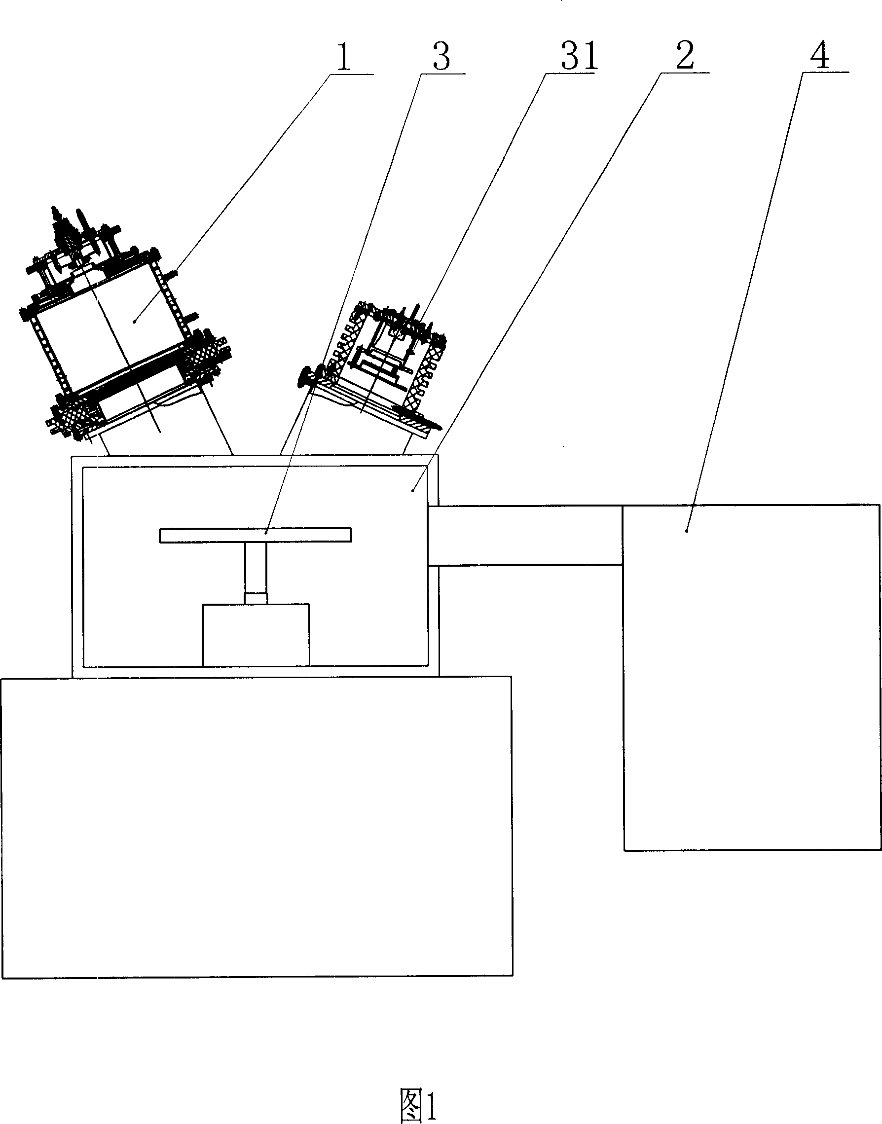
[0018] As shown in Fig. 1, Fig. 2, Fig. 3 and Fig. 4, the present invention includes a metal ion source 1, a gas ion source 31, a metal ion source power supply system, a gas ion source power supply system, a vacuum chamber 2, a workpiece target platform 3, a motor 22. Vacuum pumping system 4, cooling system, nitrogen source 25, mass flow valve 26, control panel, and gas supply system.

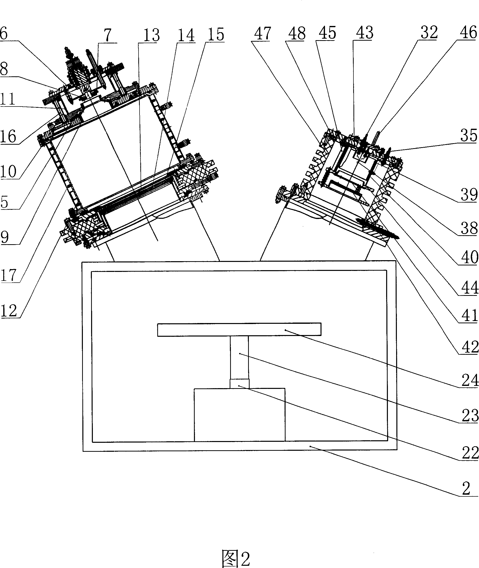
[0019] The metal ion source 1 and the gas ion source 31 are arranged on the top of the vacuum chamber 2 and communicate with the vacuum chamber 2, and the metal ion source 1 and the gas ion source 31 form an angle of 24° with the vertical direction respectively. .

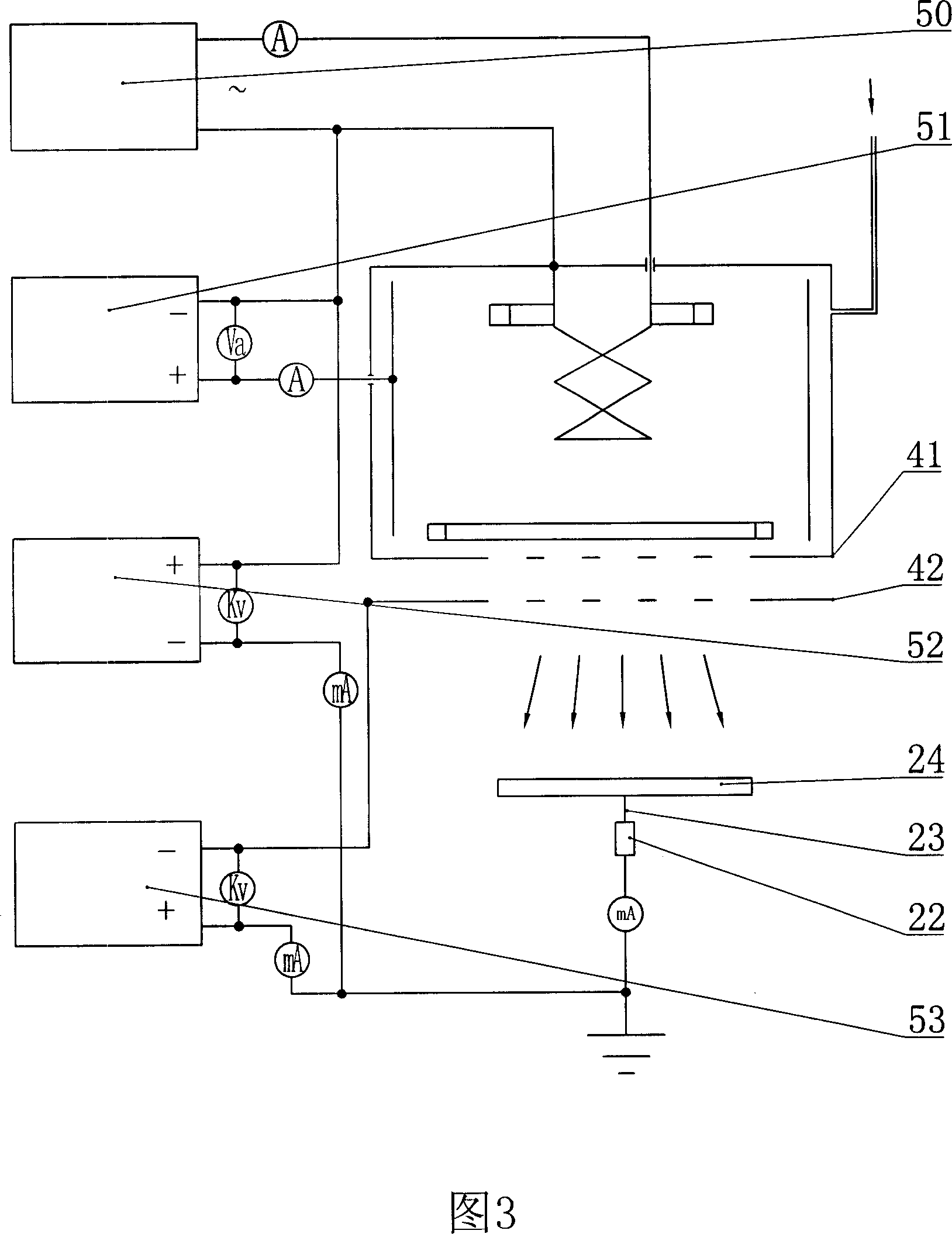
[0020] The gas ion source 31 includes a cathode terminal 32, an anode terminal 35, a filament 38, a discharge chamber 39, a discharge chamber 40, a grid 41, a second grid 42, an anode shoe 43, a cathode shoe 44, a magnetic rod 45, Air inlet 46, insulation cylinder 47, upper cover 48, described upper cover 48 is arranged on the top ...


PUM


Abstract

The disclosed metal gas mixed ion implantor comprises a metal ion source (1), an ion source power, a gas ion source (31), a gas supplying system, a gas ion source power, a vacuum chamber (2), a workpiece target platform (3), a vacuumizing system (4), a cooling system, and a control screen. This invention spreads application range of ion implantation technology greatly.

Description

technical field [0001] The invention relates to a metal gas mixed ion implanter. Background technique [0002] Conventional surface treatment technology, because it needs to be carried out in a high temperature environment, will change the overall size and surface finish of the workpiece, so that it needs to be finished after heat treatment, so it cannot meet the requirements of use, and the heat treatment layer is prone to surface peeling and peeling phenomenon. [0003] Ion implantation technology is a high-tech material surface modification developed internationally in recent years. Its basic principle is: use an ion beam with an energy of tens to hundreds of keV to enter the material, the ion beam and the material A series of physical and chemical interactions will occur in the atoms or molecules in the material, and the incident ions will gradually lose energy, and finally stay in the material, causing changes in the surface composition, structure and properties of the...

Claims


Application Information

Patent Timeline
IPC IPC(8): H01J37/317C23C14/48H01L21/265
Inventor 陶士慧马山明邵先华叶围洲蔡恩发蔡坚将吴观绵吴九妹蔡秀芳
Owner 珠海市恩博金属表面强化有限公司
Why Eureka
Try Eureka