Blast furnace cooling water backwater top pressure power generation

A residual pressure power generation and cooling water technology, which is applied in hydropower generation, cooling devices, renewable energy power generation, etc., can solve the problems of water loss and poor utilization of water conservancy resources, and achieve stable water head, stable flow, and low investment. Effect

Inactive Publication Date: 2007-08-22
王岗
View PDF0 Cites 15 Cited by
  • Summary
  • Abstract
  • Description
  • Claims
  • Application Information

AI Technical Summary

Problems solved by technology

This water conservancy resource is not well utilized in the

Method used


Image

  • Blast furnace cooling water backwater top pressure power generation
  • Blast furnace cooling water backwater top pressure power generation
  • Blast furnace cooling water backwater top pressure power generation

Examples


Embodiment Construction

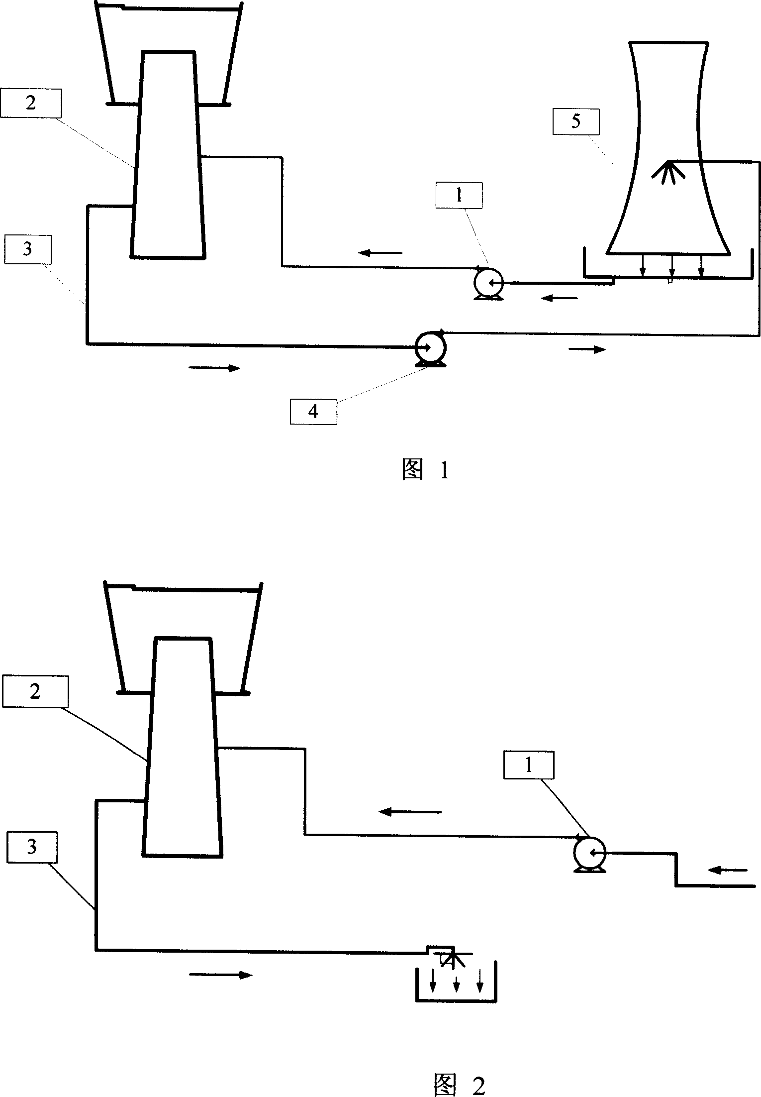
[0020] In Figure 1, the cooling water is pressurized by the water pump station (1) and sent to the blast furnace system (2) through the pipeline, and the return water flows automatically to the cooling water pump (4) through the return water pipeline (3), and is sent to the cooling water tower after being pressurized ( 5) cool down, then flow to the water pumping station (1) by itself, and use it in a closed cycle.

[0021] In Fig. 2, the cooling water is pressurized by the water pump station (1) and sent to the blast furnace system (2) through the pipeline, and the return water is freely discharged through the return water pipeline (3).

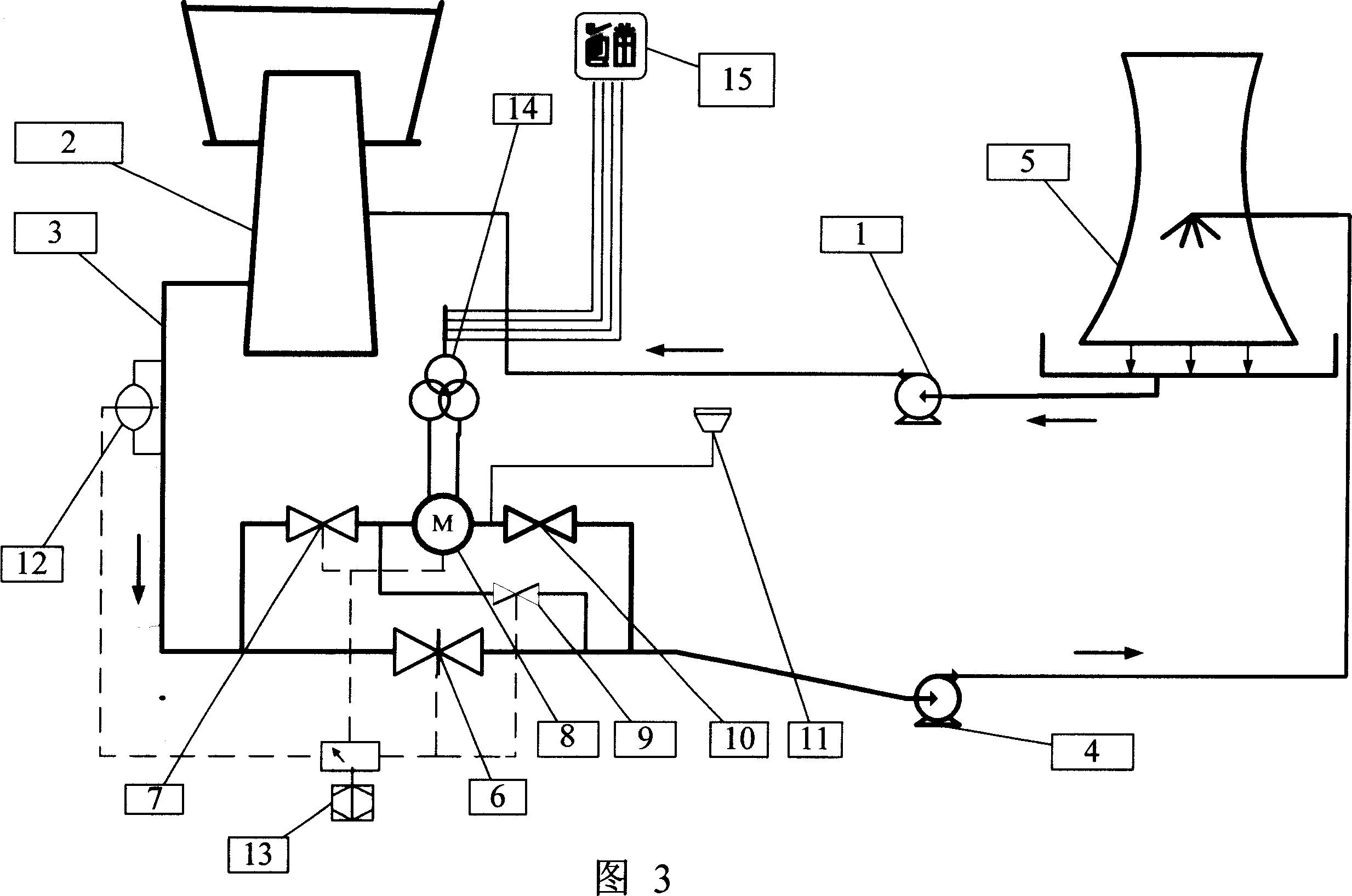
[0022] In Figure 3, the cooling water is pressurized by the water pump station (1) and sent to the blast furnace system (2) through the pipeline, and the cooling return water flows automatically to the bypass pipe hydro-generator system through the return water pipeline (3), and passes through the water inlet valve ( 7), water turbine genera...


PUM


Abstract

The present invention relates to a power generation method by utilizing iron-smelting blast furnace cooling water backwater residual pressure (water head). It is characterized by that said invention utilizes the principle of small runoff type hydroelectric generation in the blast furnace cooling backwater system, and utilizes the blast furnace cooling water backwater and makes the blast furnace cooling water backwater be flowed into cooling water pump or be freely discharged to form a height difference with about 9 m and produce a stable water resource with stable water head and stable water quantity, and utilizes the stable water resource to implement power generation. Besides, said invention also provides a technical scheme for implementing the invented power generation method.

Description

Technical field [0001] The invention relates to a method for generating electricity by utilizing the residual pressure (water head) of the return water of the ironmaking blast furnace, which is the main smelting equipment in the metallurgical industry. Background technique [0002] At present, the known blast furnace smelting process is characterized by continuous production. Therefore, it is required that the cooling water of the blast furnace must also be continuously and uninterruptedly supplied. There are two types of cooling water processes, namely: [0003] 1. Water pumping station (pressurized) → blast furnace system → return water pipe (self-flowing) → cooling water pump (pressurized) → cooling water tower → water pumping station, closed cycle use. [0004] 2. Water pump station (pressurized) → blast furnace system → return water pipe (artesian) → free discharge. [0005] Among them, when the cooling water flows from the blast furnace through the return water pipe ...

Claims


Application Information

Patent Timeline
IPC IPC(8): F03B13/00F03B15/12F03B15/14H02K7/18C21B7/10
CPCY02E10/226Y02E10/20Y02P10/20
Inventor 王岗
Owner 王岗
Why Eureka
Try Eureka