Ac motor system and method for controlling same, and related power conversion device

A technology of power conversion device and electric motor, applied in the direction of AC motor control, control system, electrical components, etc., can solve the problems of DC voltage fluctuation, uneconomical, inconsistent power, etc., and achieve the effect of increasing capacity

Active Publication Date: 2007-08-22
HITACHI LTD
View PDF1 Cites 11 Cited by
  • Summary
  • Abstract
  • Description
  • Claims
  • Application Information

AI Technical Summary

Problems solved by technology

In addition, if the rectifier cannot cope with the excessive power of the transitional method at this time, there will be inconsistency in the transmission and reception of power, and there may be a problem that the DC voltage fluctuates greatly.
[0006] In order to stabilize the operation of the system, it is important to control the DC voltage to be constant. In the prior art, by adding the power of the inverter to the rectifier in a feed-forward manner, it is possible to suppress the delay caused by the control delay of the rectifier. However, it is ineffective to control the above-mentioned DC voltage fluctuation caused by the inverter power exceeding the control capability of the rectifier.
In order to stabilize the system even under severe operation such as sudden acceleration and deceleration, it is necessary to increase the capacity of the rectifier to cope with the above-mentioned transient excess power, or to increase the capacity of the inverter to rapidly change the magnetic flux of the motor, But every method is uneconomical

Method used


Image

  • Ac motor system and method for controlling same, and related power conversion device
  • Ac motor system and method for controlling same, and related power conversion device
  • Ac motor system and method for controlling same, and related power conversion device

Examples


Embodiment 1

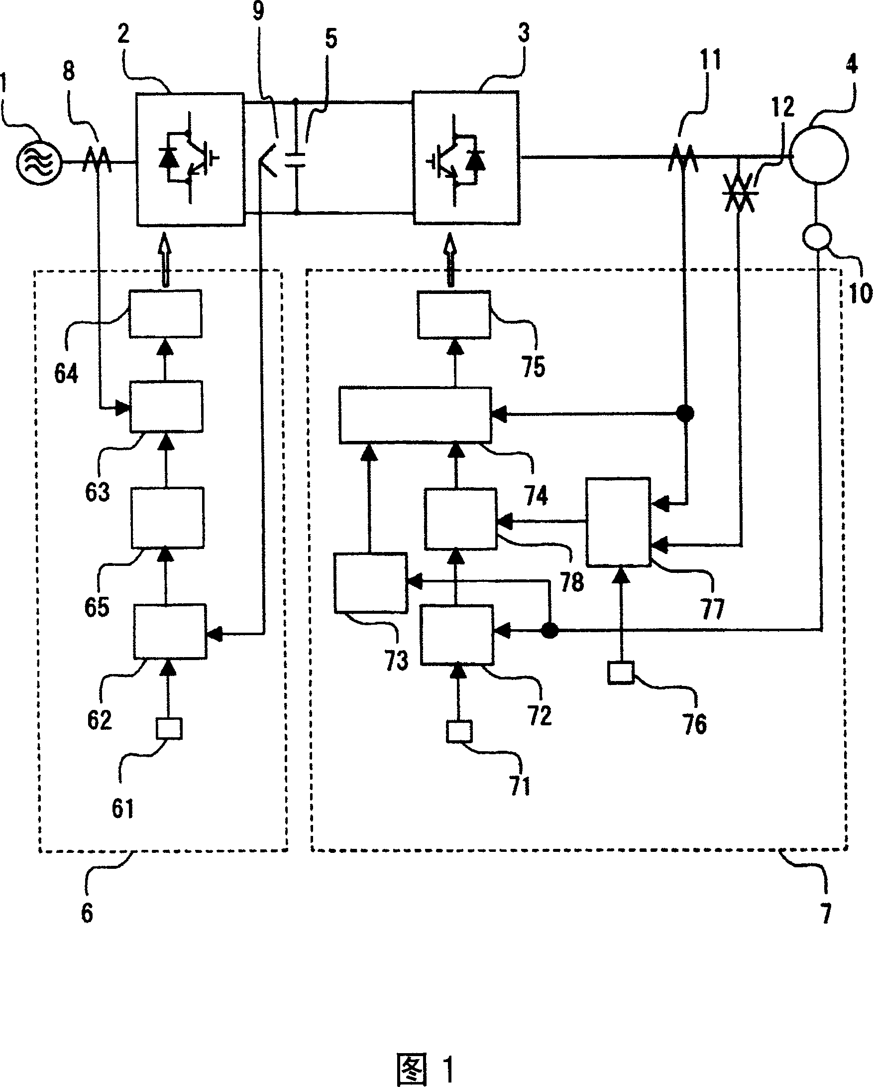
[0020] Fig. 1 is an overall configuration diagram of the present invention. 1 is an AC power supply, 2 is a rectifier that converts the AC power of the AC power supply 1 into DC power, 3 is an inverter that converts the DC power output by the rectifier 2 into desired power, and 4 is the above-mentioned An AC motor driven by the power output from the inverter 3, 5 is a smoothing capacitor provided between the rectifier and the inverter, and 6 is a rectifier control device that operates the rectifier 2 so that the DC voltage becomes a predetermined value , 7 is an inverter control device that operates the inverter 3 so that the output torque and speed of the electric motor 4 meet desired characteristics. 8 is a current detector, which detects and outputs the output current of the rectifier 2 . 9 is a voltage detector, which detects and outputs the voltage across the smoothing capacitor 5, that is, the DC voltage. 10 is a speed detector directly connected to the motor 4, which ...

Embodiment 2

[0036] Fig. 5 is another embodiment of the device of the present invention, instead of the power limit value setter 76, a power limit set value calculator 79 and a power supply voltage fluctuation detector 80 that detects the fluctuation amount of the AC power supply 1 are set, and detects The power supply voltage fluctuation amount is input to the power limit set value calculator 79, and the power limit set value is calculated in the power limit set value calculator 79 according to the power supply voltage fluctuation amount, and the calculated set value is input to The power limit computing unit 77 is different from FIG. 1 in this point. In FIG. 1 , the maximum inverter output power determined by the control capability of the rectifier is set as a fixed value in the power limit value setter 76 , but the control capability of the rectifier varies according to the operating conditions of the rectifier. For example, when the AC power supply voltage drops, the rectifier current ...

Embodiment 3

[0039] 6 is another embodiment of the device of the present invention. In the current command limiter 65 on the rectifier side, the margin of the output rectifier current command relative to the rectifier current limit value is input to the power limiter set value calculator 79 . The power limit set value calculator 79 is different from FIG. 5 in that the power limit set value is calculated based on the margin of the rectifier current command, and the calculated set value is input to the power limit calculator 77 . In FIG. 5 , only fluctuations in the rectification control capability are defined as power supply voltage fluctuations. However, although the influence of the power supply voltage fluctuation is large, other various factors such as the efficiency fluctuation of the transformer and the DC voltage fluctuation also cause the control capability to fluctuate. Therefore, due to fluctuations in the control capability of the rectifier due to these influences, the power limi...


PUM


Abstract

The objective of the invention is to provide a power conversion device for reliably restrain the switching of the dc voltage, even if in the harsh operation such as rapid acceleration-deceleration. In order to restrain the excessive inverter output power generated by flux control delay due to urgent acceleration-deceleration at the inverter side to the value corresponding to the rectifier. The processing comprises: setting the inverter output power maximum depended on the rectifier control capacity at power limiting set device, inputting the setting value of the power limiting set device, current detecting value detecting by the inverter output current detector and voltage detecting value detected by inverter output voltage detector to the power limiting calculator, calculating the torque current limiting value calculated by current detecting value and voltage detecting value, not exceeding the setting value, inputting the limiting value after calculation to the torque current order limiter, restraining the torque current order value based on the input limiting value in the torque current order limiter.

Description

technical field [0001] The present invention relates to an AC motor system, a control method of the AC motor system, and a power conversion device having a rectifier (converter) and an inverter (inverter) for driving an AC motor, and particularly relates to an AC motor system that is also suitable for harsh operations such as sudden acceleration and deceleration. An AC motor system that drives the system stably without stopping the device, a control method of the AC motor system, and a power conversion device related thereto. Background technique [0002] As a power conversion device for driving an AC motor, etc., a rectifier is used to convert the power of the AC power supply to DC, and an inverter is used to convert the DC to AC. The DC part between the rectifier and the inverter is connected. smoothing capacitor. Moreover, the control device for controlling the rectifier controls the output current of the rectifier so that the voltage across the smoothing capacitor conne...

Claims


Application Information

Patent Timeline
Patent Type & Authority Applications(China)
IPC IPC(8): H02P27/06
Inventor 秋田佳稔执行正谦
Owner HITACHI LTD
Why Eureka
Try Eureka