Fuse threading weld capper

A fuse and wire threading technology, applied in the manufacture of fuses, etc., can solve the problems of high manufacturing and maintenance costs, short life, large volume, etc., and achieve the effect of simple and reasonable structure and overcome short life

Inactive Publication Date: 2007-09-05
李风雷
View PDF0 Cites 22 Cited by
  • Summary
  • Abstract
  • Description
  • Claims
  • Application Information

AI Technical Summary

Problems solved by technology

[0004] The technical problem to be solved by the present invention is to provide an automatic assembly machine for fuses, which overcomes the shortcomings of existing machines such as short life, low efficiency, complex structure, high manufacturing and maintenance costs, and large volume

Method used


Image

  • Fuse threading weld capper
  • Fuse threading weld capper
  • Fuse threading weld capper

Examples


Embodiment Construction

[0018] A kind of specific structure of the present invention is described below in conjunction with workflow and accompanying drawing:

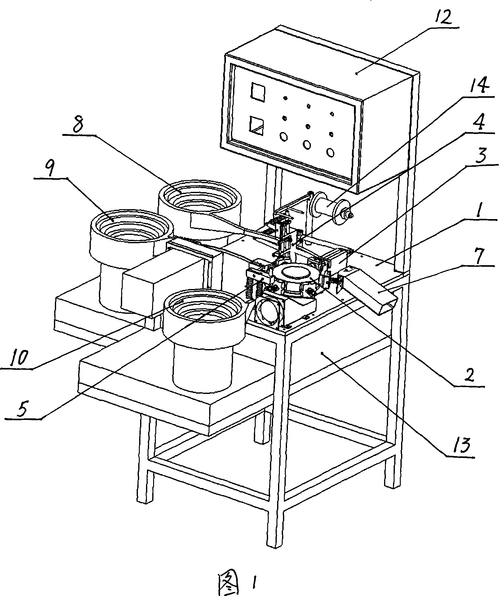
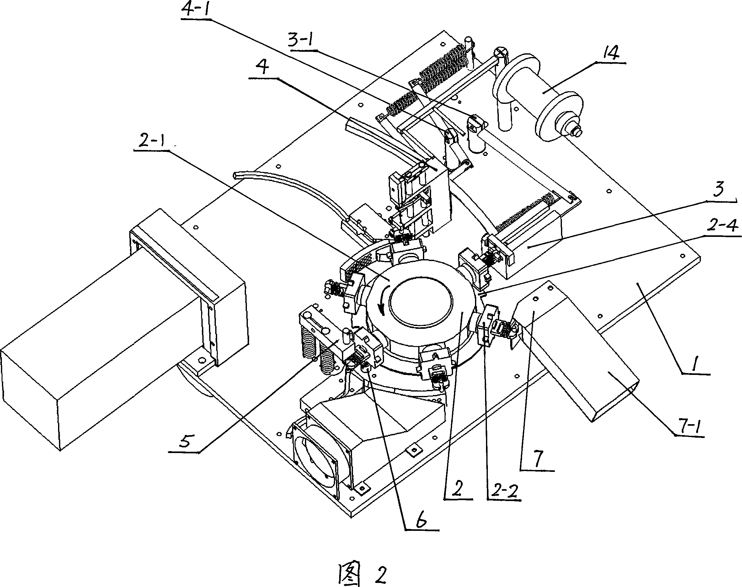
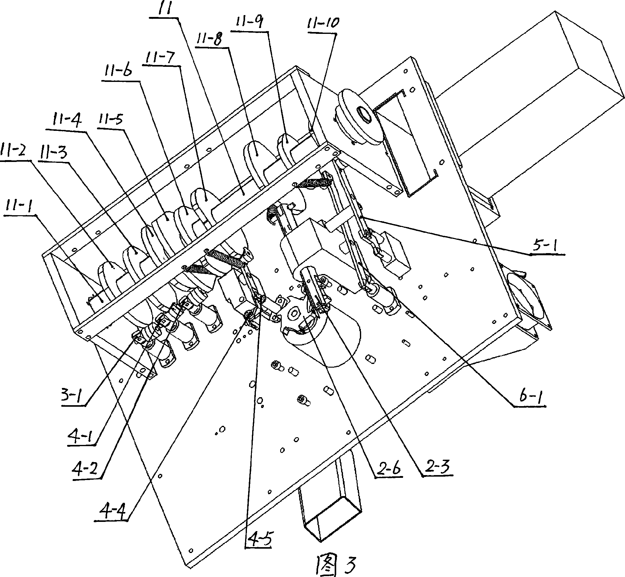
[0019] At first, as shown in accompanying drawing 1, the schematic diagram of the three-dimensional structure of the present invention has a frame, on which a horizontal workbench 1 is arranged, and an outer tube delivery device 8, an upper cap delivery device 9 and a lower cap delivery device 10 are respectively directed The outer tube, upper cap and lower cap of the fuse are transported at the station on the table 1; the assembly action mechanisms of the fuse are arranged above the workbench 1; the driving mechanism 11 for driving the action of each assembly mechanism is fixed on the back of the workbench 1, The driving mechanism 11 is built in the lubricating oil tank 13, and the driving mechanism 11 cannot be seen on the accompanying drawing 1; the transmission rods or shafts of each action mechanism pass through the workbench 1 and are co...


PUM


Abstract

The invention is concerned with a kind of process equipment for produce production, especially a kind of wire feeding welding machine with fuse for fusible core. The worktable fixed on the frame has turning plate frame with at least four tasks and the task has movable clamp extended among the radial direction, and at the corresponding position to each task, there are tube push framework, wire feeding welding upper cap framework, welding down cap framework, location framework and stuff-accepting framework on the surface of worktable. Except the stuff-accepting framework, each of the aforesaid framework drives by each cam and drive pole under the worktable. The tube push framework connects with tube feeding equipment, and the wire feeding welding upper cap framework connects with upper cap feeding equipment, the welding down cap framework connects with down cap feeding equipment. The worktable and / or turning plate has equipment that keeps clamp moving. The drive axis drives by motor, the feeding equipment, heating equipment and motor of the tube, upper cap and down cap monitors by power control equipment.

Description

technical field [0001] The invention relates to a processing device for product assembly, in particular to a fuse threading welding cap machine for melting core assembly. Background technique [0002] The fuse is composed of a fuse, an upper cap, a lower cap, and a glass or ceramic outer tube. At present, there are still many manufacturers who use manual assembly to produce it, that is, first drop solder into the upper cap and put it on the glass tube. One end of the fuse is welded to the upper cap, and then the lower cap is welded to the fuse at the other end of the glass tube by soldering tin. The disadvantages are low production efficiency, high labor intensity and unstable quality. [0003] The "Fuse Assembly Machine" disclosed in Chinese Patent Publication No. CN112048A aims to provide an automatic assembly machine for fuses. The principle of the machine can realize automatic assembly of fuses, and multiple cylinders are used to realize various feeding actions. However...

Claims


Application Information

Patent Timeline
Patent Type & Authority Applications(China)
IPC IPC(8): H01H69/02
Inventor 李风雷
Owner 李风雷
Why Eureka
Try Eureka