Fibre-optical freezing sensor

An ice sensor and optical fiber technology, applied in the field of photoelectric sensors, can solve the problems of complex signal processing, large volume and weight, poor reliability, etc., and achieve the effects of simple signal processing, good electromagnetic compatibility, and high reliability.

Inactive Publication Date: 2007-09-19
HUAZHONG UNIV OF SCI & TECH
View PDF0 Cites 17 Cited by
  • Summary
  • Abstract
  • Description
  • Claims
  • Application Information

AI Technical Summary

Problems solved by technology

[0002] The icing sensors currently used for aircraft icing detection have many shortcomings: the radiation type is harmful to human health; the conductivity type has poor reliability; the differential pressure type has a large volume and complex structure
Moreover, none of these icing sensors can give quantitative information about the severity of icing
The recent magnetostrictive vibrating cylinder and piezoelectric resonant diaphragm icing sensors can give quantitative information on the severity of icing within a certain range of ice thickness, but the volume and weight of the magnetostrictive vibrating cylinder-type icing sensors are relatively large. Large, complex structure, high production cost, can only be installed on the fuselage, not flush and conformal installed on some parts of the aircraft, such as the leading edge of the wing, and the minimum detection limit is not satisfactory (0.254mm abroad, about 0.254mm domestically) 0.300mm)
Although the volume and weight of the piezoelectric resonant diaphragm type icing sensor is small, it can be installed flush and conformal on the curved surface of the machine, and the minimum detection limit can reach about 0.10mm, which is better than the magnetostrictive vibrating cylinder type, but it has higher requirements for sensitive materials. Strict, high production cost, complex signal processing

Method used


Image

  • Fibre-optical freezing sensor
  • Fibre-optical freezing sensor
  • Fibre-optical freezing sensor

Examples


Embodiment Construction

[0015] The present invention will now be described in detail in conjunction with FIGS. 1 to 4 .

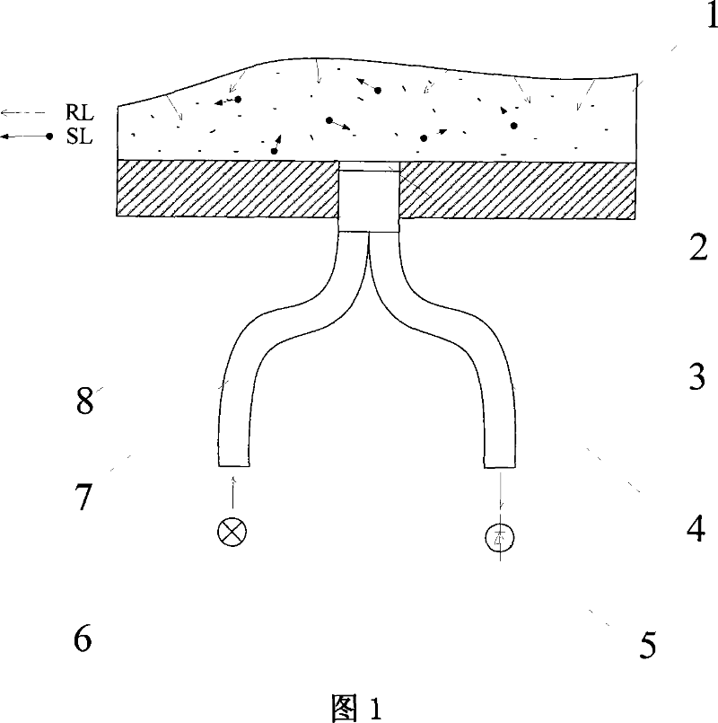
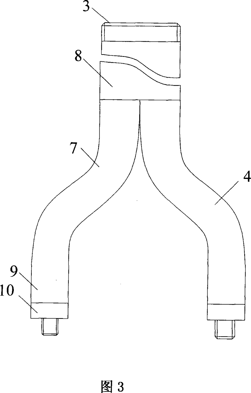
[0016] In Fig. 1, the ends of the transmitting optical fiber bundle 7 and the receiving optical fiber bundle 4 are merged into a concentrated optical fiber bundle 8, and its end face constitutes the end face 3 of the probe head, and its shape is a metal thread, which is convenient for screwing into the surface 2 of the measured object to achieve flushness installation purpose. The working wavelength of the light emitting device 6 in the transmitting circuit is near infrared, so as to eliminate the interference of the visible light in the background light to the detection circuit. When there is no icing on the surface 2 of the measured object, the emitted light from the light-emitting device 6 is transmitted along the emitting fiber bundle 7 and the concentrated fiber bundle 8 and enters the air through the end face 3 of the probe head, and the photodiode 5 cannot detect any emitte...


PUM


Abstract

The present invention provides a fiber type ice coating sensor that pertains to a photoelectric sensor and that is used for detecting the degree of the ice coating on the surface of the object. The aim of the present invention reside in making the sensor more subminiature, more light, and making a minimal sensitivity and a best lower limit performance, and making a low cost, a simple signal processing without using sensitive material. The emitting fiber beam and the receiving fiber beam in the present invention are combined to from an integrated fiber beam: the end surface of the integrated fiber beam forms the end surface of the detecting head; the other end of the emitting fiber beam is provided with an emitting circuit; the other end of the receiving fiber beam is provided with a signal detecting circuit consists of a photorectifier and a amplifying preampcircuit which are connected in series. The fiber type ice coating sensor which is suitable for detecting the degree of the ice coating on the surface of the object is small, light and in a multiple-point distribution. The fiber type ice coating sensor without detachable accessories also has a good electromagnetic compatibility, a high reliability and a simple processing of signals.

Description

technical field [0001] The invention belongs to a photoelectric sensor, in particular to an optical fiber type icing sensor, which is used for detecting the icing condition on the surface of an object. Background technique [0002] The icing sensors currently used for aircraft icing detection have many shortcomings: the radiation type is harmful to human health; the conductivity type has poor reliability; the differential pressure type has a large volume and complex structure. Moreover, none of these icing sensors can give quantitative information about the severity of icing. The recent magnetostrictive vibrating cylinder and piezoelectric resonant diaphragm icing sensors can give quantitative information on the severity of icing within a certain range of ice thickness, but the volume and weight of the magnetostrictive vibrating cylinder-type icing sensors are relatively large. Large, complex structure, high production cost, can only be installed on the fuselage, not flush ...

Claims


Application Information

Patent Timeline
Patent Type & Authority Applications(China)
IPC IPC(8): G01D5/353
Inventor 叶林张杰张洪李薇
Owner HUAZHONG UNIV OF SCI & TECH
Why Eureka
Try Eureka