Voltage-stabilizing switch power source with voltage ripple detection circuit

A voltage ripple and detection circuit technology, applied in the field of electronics, can solve the problems of decreased power supply efficiency, consume extra power, increase system cost and volume, etc., and achieve the effects of low system cost, small power supply volume, and high power supply efficiency

Inactive Publication Date: 2007-09-19
UNIV OF ELECTRONICS SCI & TECH OF CHINA
View PDF0 Cites 26 Cited by
  • Summary
  • Abstract
  • Description
  • Claims
  • Application Information

AI Technical Summary

Problems solved by technology

[0004] The disadvantages of commonly used switching regulated power supply systems are: 1. The output voltage detection network needs to consume extra power, resulting in a decrease in power supply efficiency; 2. In AC/DC converters, the input circuit and output circuit are

Method used


Image

  • Voltage-stabilizing switch power source with voltage ripple detection circuit
  • Voltage-stabilizing switch power source with voltage ripple detection circuit
  • Voltage-stabilizing switch power source with voltage ripple detection circuit

Examples


Embodiment approach 1

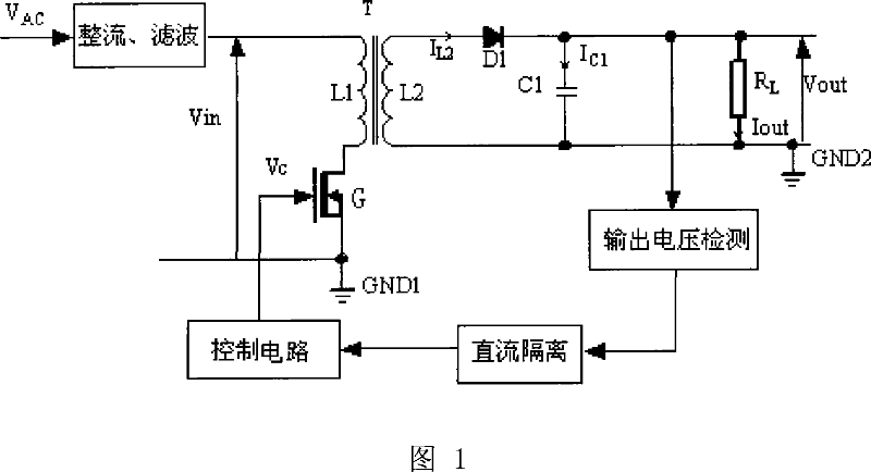
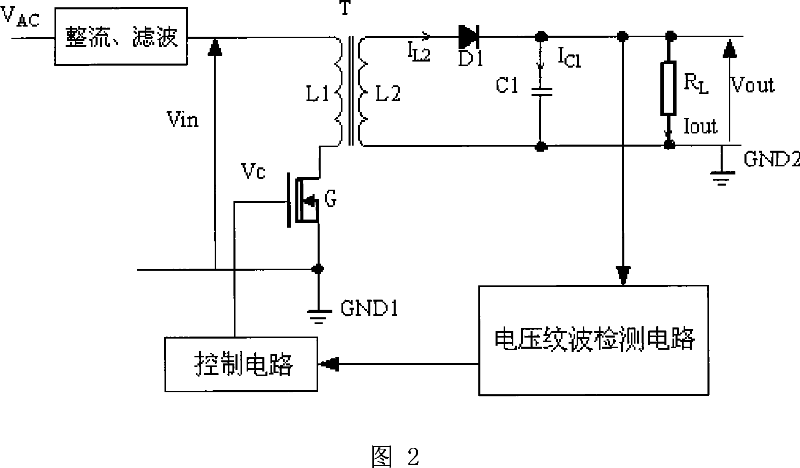
[0041] The regulated switching power supply with voltage ripple detection circuit, as shown in Figure 2, includes rectification and filter circuits, transformer T, power switch tube G, control circuit, freewheeling diode D1, output filter capacitor C1, load RL and voltage ripple wave detection circuit. Input voltage V AC Connect to one end of transformer T secondary inductance L1 through a rectifier and filter circuit, the other end of transformer T secondary inductance L1 is connected to the drain of power switch G, the drain and source of power switch G are connected to input stage ground GND1, the power The gate of the switching tube G is connected to the output terminal of the control circuit; one end of the secondary inductor L2 of the transformer T is connected to the anode of the freewheeling diode D1, and the cathode of the freewheeling diode D1 is connected to one end of the parallel connection between the output filter capacitor C1 and the load RL, and the secondary ...

Embodiment approach 2

[0051] The regulated switching power supply with voltage ripple detection circuit, as shown in Figure 2, includes rectification and filter circuits, transformer T, power switch tube G, control circuit, freewheeling diode D1, output filter capacitor C1, load RL and voltage ripple wave detection circuit. Input voltage V AC Connect to one end of transformer T secondary inductance L1 through a rectifier and filter circuit, the other end of transformer T secondary inductance L1 is connected to the drain of power switch G, the drain and source of power switch G are connected to input stage ground GND1, the power The gate of the switching tube G is connected to the output terminal of the control circuit; one end of the secondary inductor L2 of the transformer T is connected to the anode of the freewheeling diode D1, and the cathode of the freewheeling diode D1 is connected to one end of the parallel connection between the output filter capacitor C1 and the load RL, and the secondary ...


PUM


Abstract

The invention provides a voltage regulation switch power supply relating to electric technique field. The power supply output voltage dc amount is detected by a voltage ripple detecting circuit and fed back to a control circuit to control the turn-on and turn-off of the power switch tube thus to realize regulated output. The voltage ripple detecting circuit of the voltage regulation switch power supply provided by this invention comprises a high pass filtering module, a second order differentiation operation module, a linear operation module, and a clock gating/signal memory module which are connected in series sequentially. The voltage ripple of the voltage regulation switch power supply output voltage is firstly extrated and then performed by second order differentiation, linear operation and memory extension to 'resume' the dc output voltage of the voltage regulation switch power supply which is finally fed back to PWM, PFM or PSM control ciucuit so as to realize regulated output via adjusting the turn-on and turn-off of the power switch tube by the control circuit. The present invention has higher power efficiency and lower circuit cost as well as smaller power supply volume compared with prior voltage regulation switch power supply.

Description

technical field [0001] The invention belongs to the field of electronic technology, and relates to a voltage-stabilized switching power supply, in particular to a voltage-stabilized switching power supply for output voltage detection and control. Background technique [0002] The basic working principle of the switching regulated power supply is that in the case of input voltage changes, internal parameters changes, and external load changes, the control system detects the controlled output voltage signal and feeds the signal back to the PWM, PFM or PSM control mode. The closed-loop feedback adjusts the turn-on and turn-off time of the main circuit power switching device, so that the output voltage of the switching power supply is stable. [0003] Figure 1 shows an existing AC / DC regulated switching power supply with transformer isolation. In the input stage of the main circuit, VAC is the AC input voltage, typically 220V, and Vin is the line input voltage rectified by the ...

Claims


Application Information

Patent Timeline
IPC IPC(8): H02M3/335
Inventor 李泽宏周春华赖昌菁刘曦麟
Owner UNIV OF ELECTRONICS SCI & TECH OF CHINA
Why Eureka
Try Eureka