

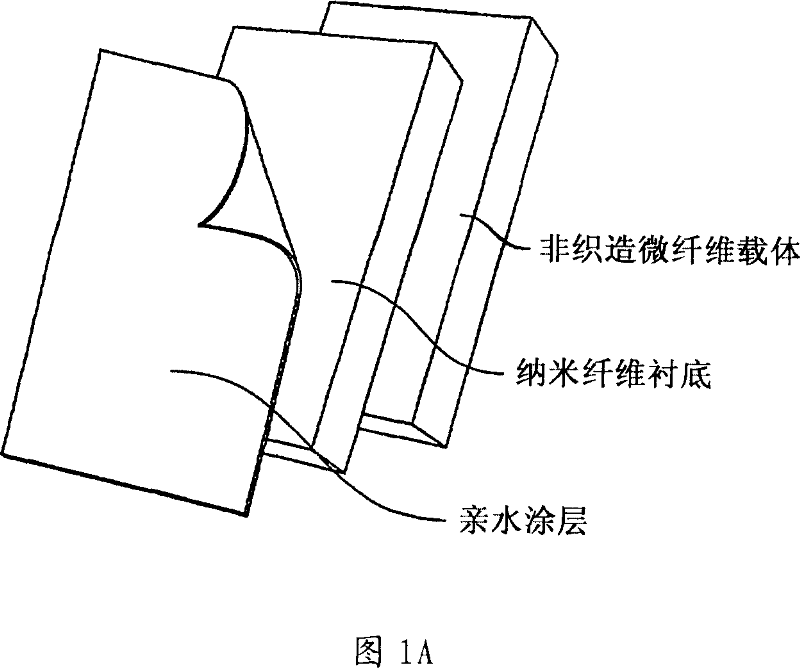
High flux and low fouling filtration media
A kind of product and polymer technology, applied in the field of high flux and low fouling filter media, can solve the problems of high operating cost and insufficient response
- Summary
- Abstract
- Description
- Claims
- Application Information
AI Technical Summary
Problems solved by technology
Method used
Image

Examples
Embodiment 1
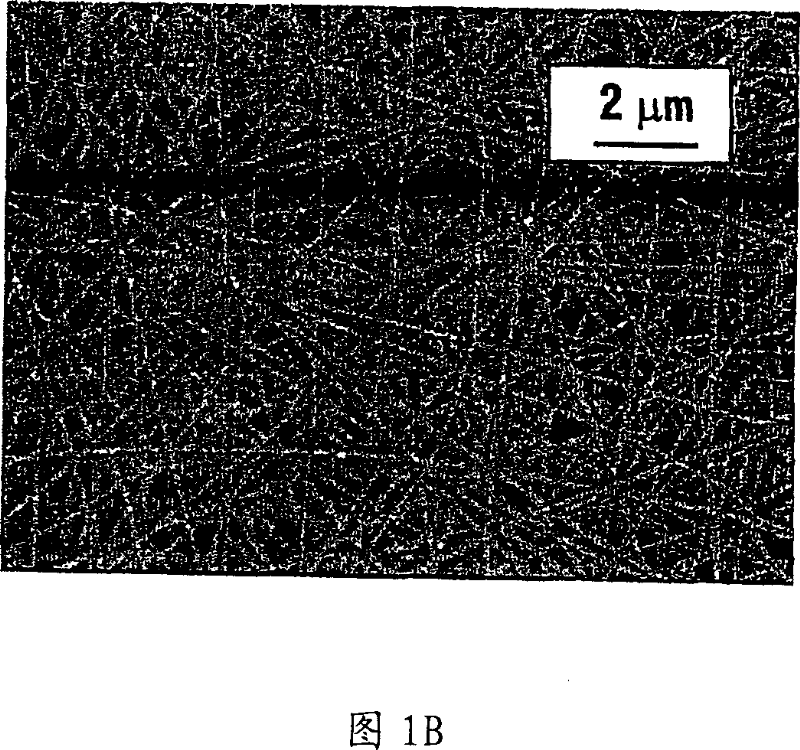
[0105] Formation of polyacrylonitrile interlayer. According to the present disclosure, a polyacrylonitrile (PAN, Mw~150,000) / dimethylformamide (DMF) (10 wt%) solution was used to fabricate a porous middle layer for a filter. The electrospinning parameters are as follows: the applied voltage is about 14 to about 20 kV; the flow rate is about 10 to about 20 μl / min; the spinneret diameter is about 0.7 mm; the distance between the collector (PET substrate) and the spinneret is about 10 to about 18cm. In order to control the porosity of the electrospun membrane and to facilitate carrying the top coat, it is desirable to vary the diameter of the electrospun fibers within physical limits (eg, approaching the entanglement concentration or solubility limit). To control PAN electrospun fiber diameter, PAN solutions at various concentrations (about 4 to about 12 wt% in DMF) were used. The sizes obtained from the various solutions are summarized in Table 1 below.
[0106] ...
Embodiment 2
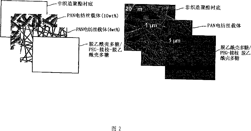
[0110] Improved bonding of electrospun layers and microfiber substrates. One side of a PET substrate FO2413 (commercially obtained from Freudenburg Nonwovens (Hopkinsville, KY) with a fiber diameter of about 10 μm) was coated with a 0.7 wt % aqueous solution of neutral chitosan (Mw = 200,000 g / mol). The PAN solution (10 wt%) was directly electrospun onto the chitosan coating before the chitosan coating applied on the substrate was completely dried. After electrospinning PAN, the composite ultrafilter (microfilter / electrospinning PAN hybrid) was vacuum dried at room temperature for 2 days.
[0111] The resulting membranes were processed with a cross-flow filtration unit based on standard filtration equipment from Pall Corporation for the UF industry. This instrument offers the following test ranges:
[0112] 1. Filter size: 2.75in×3.75in
[0113] 2. Pump flow rate: 1.25 gallons per minute (GPM). Its pressure can develop up to 500psi
[0114] 3. The size of the inlet, outle...
Embodiment 3
[0118] Design and testing of nanofibrous scaffold-based high-flux membranes. Poly(acrylonitrile) (PAN) electrospun membranes of different thicknesses (50-300 μm) were used as interlayer membranes and applied to PET-type substrates treated with chitosan as described in Example 2. .
[0119] The following materials were used in the preparation of nanofibrous membranes.
[0120] (A) Polyester substrate: nonwoven PET microfilter (FO2413, Freudenburg Nonwovens). The average fiber diameter in the substrate is about 10 μm.
[0121] (B) PAN (polyacrylonitrile) from Aldrich was used to fabricate nanofibrous scaffolds using the following electrospinning method. In DMF, prepare 8-10 wt% PAN solution. The PAN solution was electrospun on the surface of the PET substrate at 18 kV with a solution flow rate of 25 μm / min. The thickness of electrospun PAN ranged from 50 μm to 300 μm.
[0122] (C) Two commercially available ultrafiltration (UF) membrane systems were selected to compare flu...
PUM
| Property | Measurement | Unit |
|---|---|---|
| diameter | aaaaa | aaaaa |
| thickness | aaaaa | aaaaa |
| length | aaaaa | aaaaa |
Abstract
Description
Claims
Application Information