
Sun simulation device based on integrating-sphere

A sun simulation and integrating sphere technology, applied in lighting devices, lighting device components, lamp circuit layout, etc., can solve problems such as energy loss, relative spectral composition difference, system error, etc., and achieve temperature drift suppression and high stability Effect

Inactive Publication Date: 2007-09-26
FUDAN UNIV
View PDF0 Cites 8 Cited by
  • Summary
  • Abstract
  • Description
  • Claims
  • Application Information

AI Technical Summary

Problems solved by technology

[0003] In order to meet condition 1, traditional solar simulators mainly use complex optical systems, but the design of optical systems is generally based on point light sources, and the actual light source always has a certain size, which will bring certain errors to the system
In addition, there is a certain difference in the relative spectral composition of the currently available light sources and sunlight
In order to eliminate this difference, traditional solar simulators generally use filters to adjust the spectral composition of the output, but this will cause a lot of energy loss
Therefore, traditional solar simulators can rarely satisfy the above three conditions at the same time

Method used


Image

  • Sun simulation device based on integrating-sphere
  • Sun simulation device based on integrating-sphere

Examples


Embodiment 1

[0016] Embodiment 1 Solar Simulator A

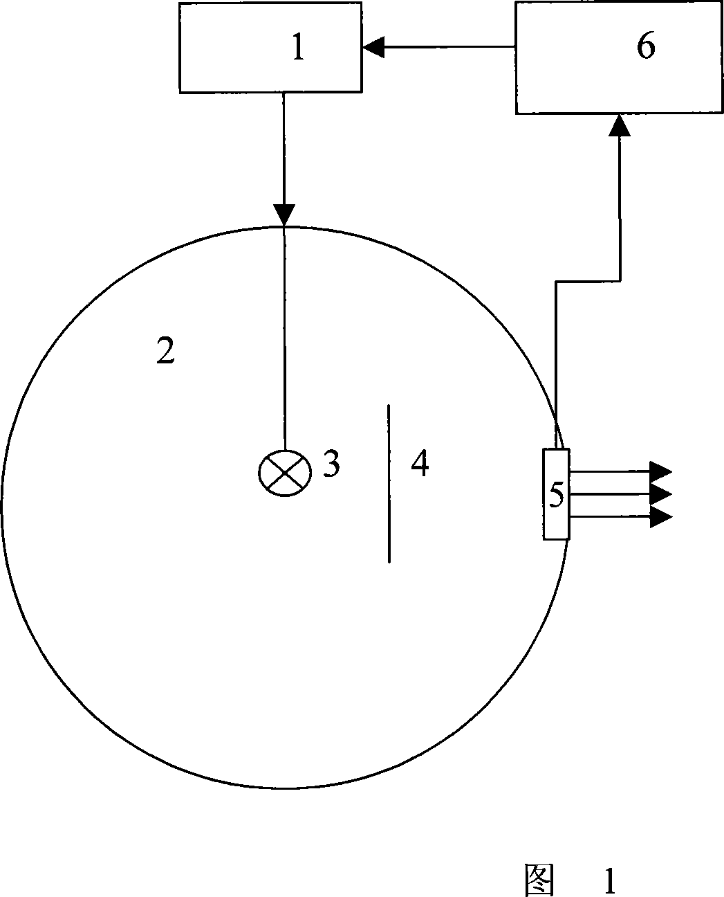
[0017] As shown in Figure 1, the components used in each part of the solar simulator are as follows:

[0018] Light source: xenon lamp

[0019] Integrating sphere: use a sphere with an inner wall reflectivity of 99%.

[0020] Power supply: 220V regulated power supply.

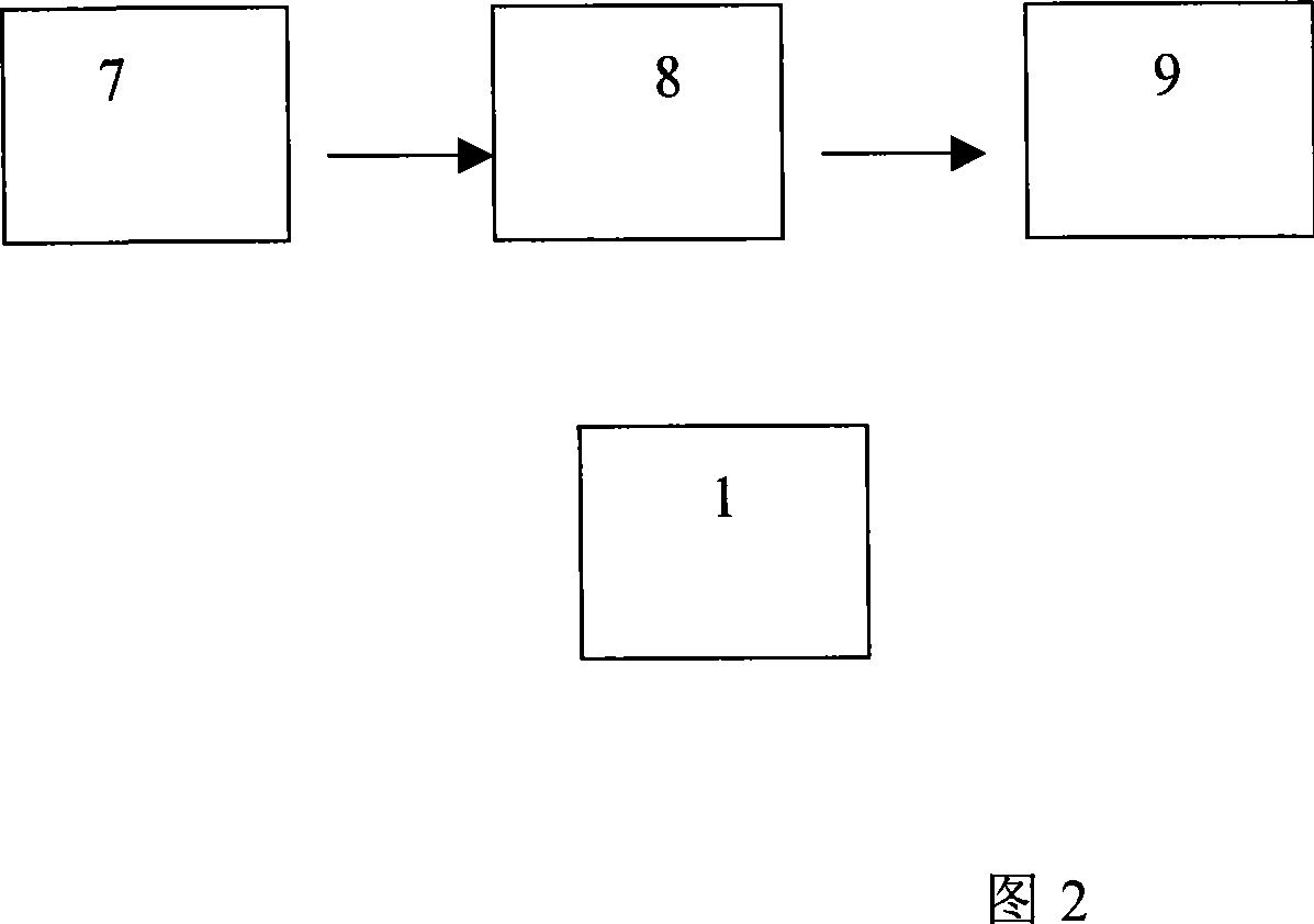
[0021] Feedback device: It is composed of photodetector, amplifier circuit and power control circuit. The photodetector detects the light intensity of the light source, and controls the output of the power supply through the feedback of the amplifying circuit, see Figure 2.

[0022] The whole assembly process:

[0023] The light source 3 is placed at the center of the integrating sphere, and a hole is opened at the wall of the integrating sphere 2 as a light window 5 . The shielding screen 4 is placed between the center of the integrating sphere 2 and the light window 5, and the distance from the center of the sphere is one-third of the radius of the integrating sphe...

Embodiment 2

[0024] Example 2 Solar Simulator B

[0025] As shown in Figure 1, the components used in each part of the solar simulator are as follows:

[0026] Light source: high-power halogen tungsten lamp plus ultraviolet lamp.

[0027] Integrating sphere: A ball with an inner wall reflectivity of 99% is used, and a hole is opened on the wall of the ball to place the light source.

[0028] Power supply: 12V DC regulated power supply.

[0029] Feedback device: It can be composed of photodetector, amplifier circuit and power control circuit.

[0030] The whole assembly process:

[0031] The light source 3 is placed on the wall of the integrating sphere, and a hole is opened at the wall of the integrating sphere 2 as a light window 5 . The shielding screen 4 is placed between the center of the integrating sphere 2 and the light window 5, and the distance from the center of the sphere is one-third of the radius of the integrating sphere. The light window of the integrating sphere is use...


PUM


Abstract

It relates to a photoelectric analog equipment.It comprises the power, integrating sphere, light source, baffle screen, light window and feedback device. The power ignites the light source that locates at the spherical center of the integrating sphere or the ball wall, the light window being a hole open at the integrating sphere wall, the baffle screen inside the integrating sphere, and the light source and the light window at both sides of the baffle screen and the light window connected with the feedback device and the electric power. It makes full use of integrating sphere to output even light to realize the fine analog of solar output.

Description

technical field [0001] The invention belongs to the sunlight simulation equipment technology, and in particular relates to a sun simulation device based on an integrating sphere. Background technique [0002] There are three main conditions for realizing high-precision simulated sun (level A): 1. The spatial uniformity of the output light should be good; 2. The relative spectral composition of the output light should be consistent with that of sunlight; 3. The temperature drift of the output should be small. [0003] In order to satisfy condition 1, the traditional solar simulator mainly uses a complex optical system, but the design of the optical system is generally based on a point light source, and the luminous point of the actual light source always has a certain size, which will bring a certain error to the system. In addition, the relative spectral composition of currently available light sources and sunlight has certain differences. In order to eliminate this differe...

Claims


Application Information

Patent Timeline
IPC IPC(8): F21S2/00F21V7/10F21V11/08H05B35/00H05B37/02H01J61/16H01K1/50
Inventor 张万路李文宜袁川刘木清周小丽
Owner FUDAN UNIV
Learn More