Photoelectric heterodyne detection circuit

A technology of heterodyne detection and photodetector, applied in the direction of heterodyne/beat frequency comparison, electrical components, frequency measurement devices, etc., can solve the problems of increasing the difficulty of optical path adjustment and system volume, increasing the difficulty of data processing, and increasing system volume, etc. Achieve the requirements of reducing sampling frequency and the difficulty of data processing, low cost, and reduce the effect of system volume

Inactive Publication Date: 2007-09-26
SHANGHAI INST OF OPTICS & FINE MECHANICS CHINESE ACAD OF SCI
View PDF0 Cites 6 Cited by
  • Summary
  • Abstract
  • Description
  • Claims
  • Application Information

AI Technical Summary

Problems solved by technology

When the mirror or other devices in the measurement device move to the boundary conditions they may reach, the frequency shift cannot be maintained infinitely, which will cause a short-term loss of the beam or a phase jump. At the same time, it can be seen from Figure 1: The device uses APD, multiple beam splitters and other optical components to achieve frequency shift and phase detection, which increases the di...

Method used


Image

  • Photoelectric heterodyne detection circuit
  • Photoelectric heterodyne detection circuit
  • Photoelectric heterodyne detection circuit

Examples


Embodiment Construction

[0038] The present invention will be further described below in conjunction with drawings and embodiments. But it should not limit the protection scope of the present invention.

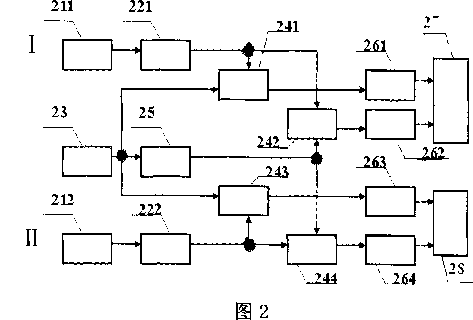
[0039] Please refer to FIG. 2 first. FIG. 2 is a schematic structural diagram of an embodiment of the photoelectric heterodyne detection circuit of the present invention. As can be seen from the figure, the photoelectric heterodyne detection circuit of the present invention comprises a first photodetector 211, a second photodetector 212, a first high-pass filter 221, a second high-pass filter 222, a local oscillator 23, a first mixing Frequency mixer 241, second mixer 242, third mixer 243, fourth mixer 244, 90° phase shifter 25, first low-pass filter 261, second low-pass filter 262, third Low-pass filter 263, the 4th low-pass filter 264, data acquisition card 27, oscilloscope 28 constitute signal processing circuit I and reference processing circuit II, and its positional relationship is:

[0040] ...


PUM


Abstract

This invention relates to one electricity photo outer difference detection circuit to realize underwater sound communication, which comprises first detector, second one, first high pass filter, second filter, local oscillator, first mixture device, second device, third one, fourth one, ninety displacement device, first low pass filter, second one, third one, fourth one, data collection card, wave display device to form signal process circuit and reference process circuit.

Description

technical field [0001] The invention relates to photoelectric signals, in particular to a photoelectric heterodyne detection circuit for acousto-optic communication with an underwater target, which is a circuit for realizing photoelectric heterodyne detection by only using electronic devices. Background technique [0002] With the rapid development of laser Doppler vibration measurement technology, it has the precision and sensitivity that cannot be achieved by ordinary methods, and can measure the movement speed and small changes of various weak vibration targets in a long-distance and non-contact manner. The high precision, strong anti-interference ability, and good confidentiality of laser Doppler vibration measurement technology make it used in communication with underwater targets, and it is a powerful technical means to obtain underwater target information. [0003] The development of laser Doppler vibration measurement technology depends not only on the long-term deve...

Claims


Application Information

Patent Timeline
IPC IPC(8): G01R23/14H03D7/00
Inventor 尚建华贺岩陈卫标臧华国
Owner SHANGHAI INST OF OPTICS & FINE MECHANICS CHINESE ACAD OF SCI
Why Eureka
Try Eureka