Wheel-support rolling bearing unit

A technology for rolling bearings and wheels, which is applied to bearing elements, axles, wheels, etc., can solve the problems of increased resistance to deformation load and deformation, achieve the effect of improving wear resistance and hardness, and improving rolling fatigue life

Inactive Publication Date: 2007-10-03
NSK LTD
View PDF5 Cites 10 Cited by
  • Summary
  • Abstract
  • Description
  • Claims
  • Application Information

AI Technical Summary

Problems solved by technology

[0030] However, if the deformation load and deformation resistance at the time of riveting increase, the above-mentioned problems may not be solved in the technology described in the above-mentioned gazette.

Method used


Image

  • Wheel-support rolling bearing unit
  • Wheel-support rolling bearing unit
  • Wheel-support rolling bearing unit

Examples


no. 1 approach

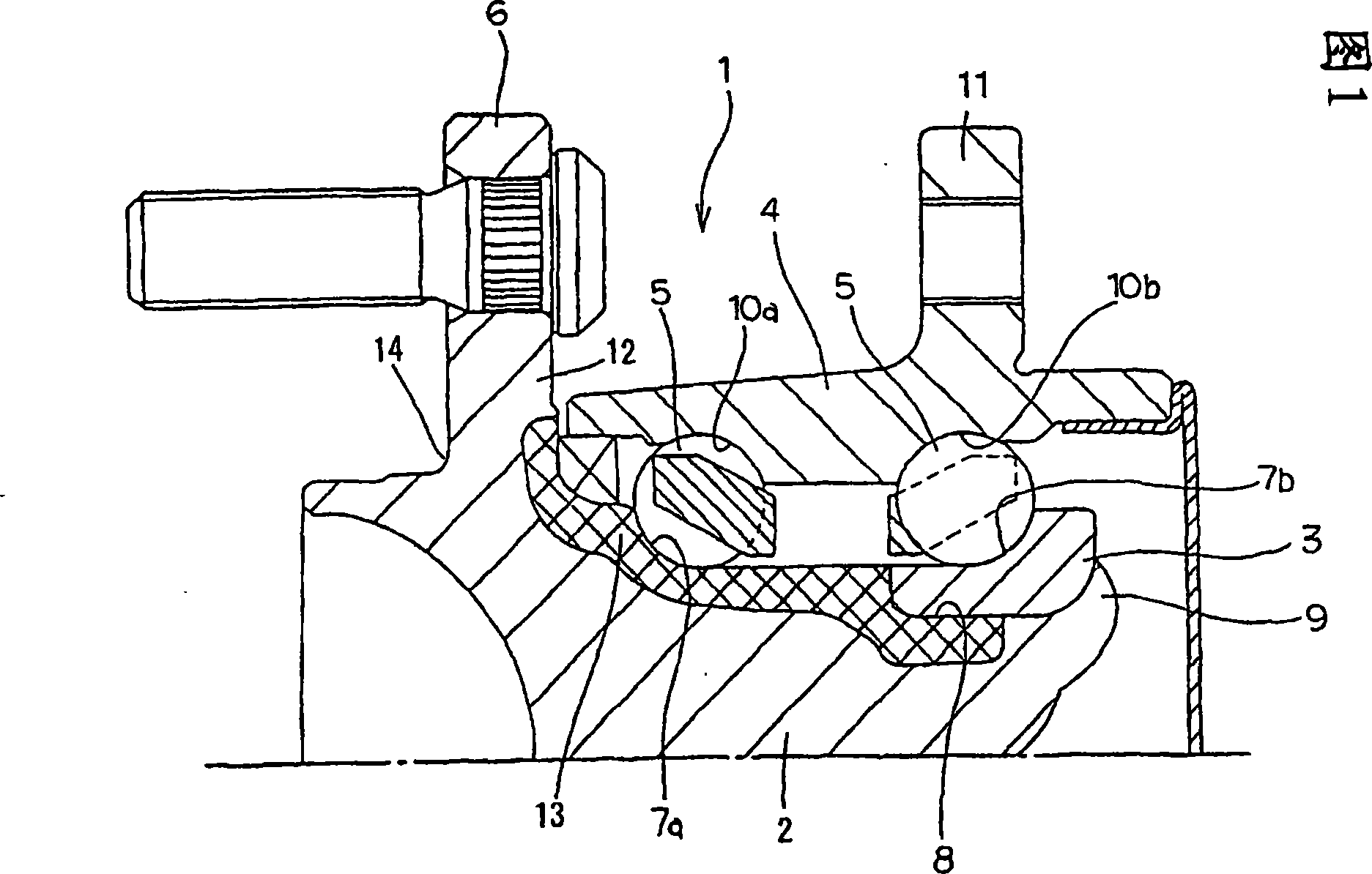
[0236] In the flanged bearing device 1 , since the hub wheel 2 is in a rotating state, a radial load from the road surface is applied to the bearing, and rotational bending stress is generated at the base of the wheel mounting flange 6 . In particular, since the outer root portion 14 of the wheel mounting flange 6 is not subjected to heat treatment such as quenching, rotational bending stress is concentrated, and therefore, there is a risk of damage depending on usage conditions or design conditions.

[0237] On the one hand, as described above, since the weight of the hub 2 is required to be reduced, the thickness of the wheel mounting flange 6 is preferably reduced. However, in order to increase the thickness reduction of the wheel mounting flange 6 , it is necessary to increase the fatigue strength of the root portion 14 on the outer side of the wheel mounting flange 6 .

[0238] On the outer root portion (non-tempered portion) 14 of the wheel mounting flange 6 that is not ...

no. 1 example

[0292] In order to confirm the effects of the present invention, the raw materials shown in Table 7 were processed under various hot forging conditions, the microstructure was confirmed, and the amount of proeutectoid ferrite was measured by image analysis.

[0293] steel type

C

(weight%)

Si

(weight%)

mn

(weight%)

Cr

(weight%)

V

(weight%)

S

(weight%)

S53C

0.53

0.21

0.75

0.17

0

0.017

A1

0.54

0.24

0.79

0.15

0

0.013

A2

0.53

0.22

0.81

0.16

0

0.005

A3

0.45

0.22

0.81

0.16

0

0.013

A4

0.65

0.22

0.81

0.16

0

0.013

A5

0.56

0.24

0.79

0.15

0.08

0.013

B1 ...

no. 2 example

[0324] In order to confirm the effects of the present invention, the following experiments were conducted.

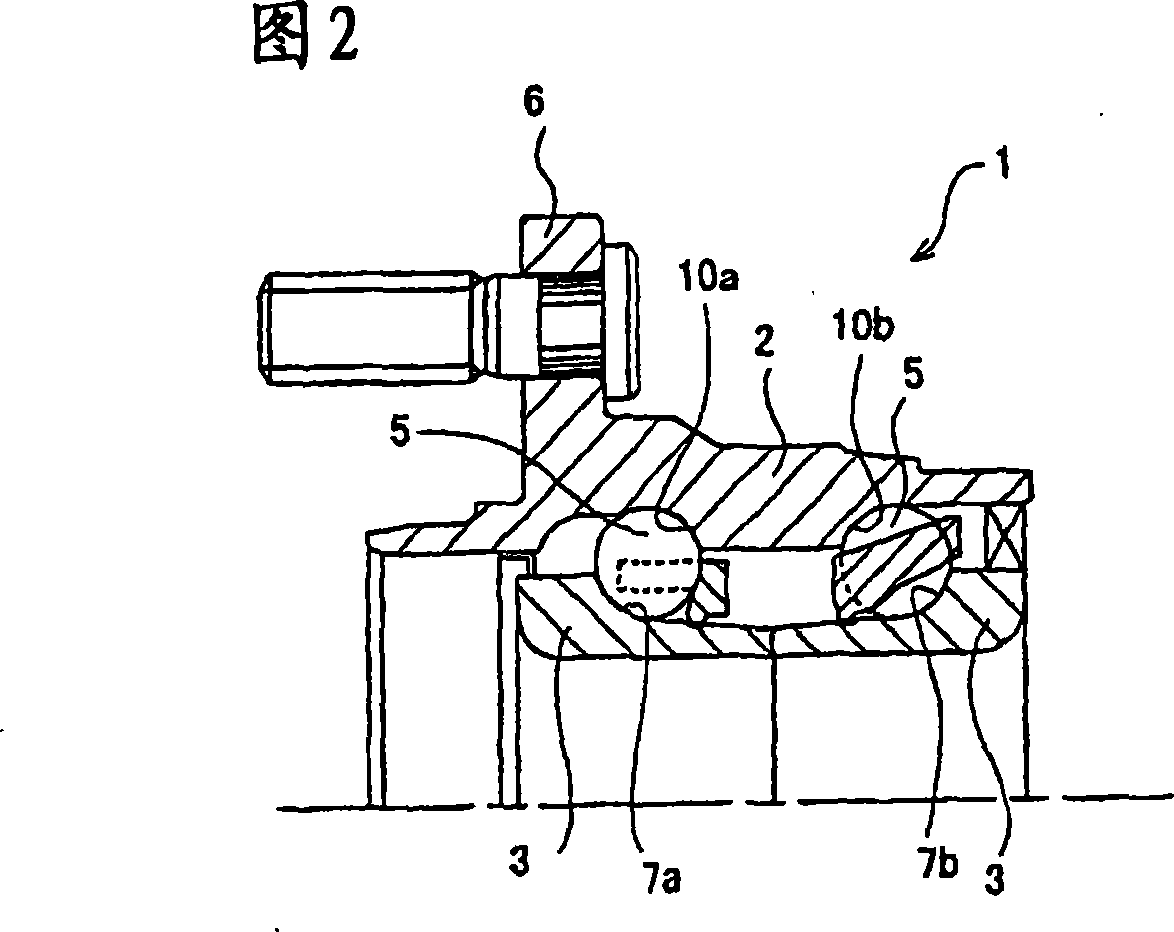
[0325] First, using the rod-shaped raw materials of components A to D in Table 9, each rod was cut, and then formed into a predetermined shape by high-frequency induction heating and hot forging at a temperature of 950 to 1200° C., respectively. Then, forced air cooling or natural cooling, after removal of the oxide film by a shot blasting machine, turning, high-frequency induction hardening and grinding of the raceway surface, the hub ring 2 shown in FIG. 9 is produced.

[0326] In addition, as the hub ring 2, the hub rings in Examples 22 to 30 in Table 10 and Comparative Examples 7 to 11 were prepared. In addition, as the hub wheels 2 of Examples 22 to 30, those subjected to the above-mentioned distribution control of proeutectoid ferrite were used.

[0327] Element

C

(weight%)

Si

(weight%)

mn

(weight%)

Cr

(weight%)...


PUM

PropertyMeasurementUnit
hardnessaaaaaaaaaa
hardnessaaaaaaaaaa
hardnessaaaaaaaaaa

Abstract

In a wheel-support rolling bearing unit, in order to made a flange 6 thinner and thus lighten the bearing unit without impairing fatigue strength, machinability, and workability after forging, the composition of the alloy steel constituting the flange attached member (hub ring 2), the surface hardness of the root portion 14 on the axial outside surface side of the flange 6, and the surface roughness, are stipulated to thereby improve the durability ratio (fatigue limit strength/tensile strength) of the flange 6. In one aspect, the member is made from an alloy steel containing C: 0.5 to 0.65 weight %, Mn: 0.3 to 1.5 weight %, Si: 0.1 to 1.0 weight %, Cr: 0.01 to 0.5 weight %, S: 0.35 weight % or less, and any one type or more selected from 0.01 to 0.2 weight % of V, 0.01 to 0.15 weight % of Nb, and 0.01 to 0.15 weight % of Ti, with the rest being Fe and inevitable impurities, and the oxygen contents is 15ppm or less. Moreover, the surface hardness of the inner raceway 7a formed with the hardened layer, is between Hv 650 and 780, and the surface hardness of a portion not formed with the hardened layer is between Hv 230 and 300.

Description

[0001] This application is a divisional application of the patent application whose application number is 038210320 (international application number is PCT / JP03 / 08977), the application date is July 15, 2003, and the application name is "rolling bearing unit for wheel support". technical field [0002] The present invention relates to an improvement of a rolling bearing unit for a wheel. The purpose is to rotatably support the wheel of an automobile on a suspension device. In particular, it has a flange for bonding and fixing a part of the wheel or the suspension device to the peripheral surface, and has at least Improvement of rolling bearing units for wheels with an inner member (also called an inner ring) or an outer member (also called an outer ring) with a hardened layer formed on the track portion (inner ring track or outer ring track). Background technique [0003] In order to rotatably support the wheel of the automobile on the suspension device, the rolling bearing u...

Claims


Application Information

Patent Timeline
Patent Type & Authority Applications(China)
IPC IPC(8): F16C19/02F16C33/62F16C35/04B60B35/18B60B27/00C22C38/00C22C38/24C22C38/04C22C38/18C22C38/26C22C38/14C21D9/40
Inventor 宇山英幸宫本祐司冲田滋
Owner NSK LTD
Why Eureka
Try Eureka